Configuration
7-90
48XX/49XXSHB0399
If the inputs are not assigned, constant values can be assigned via the input
codes. These values can also be stored in EEPROM via C003.
2. Function
The additional torque set-values have a summing influence on the n controller
output. The sum of these signals is limited to 100%.
Code Name
Possible settings
Lenze Selection Info
C148 Additional
torque
value 1
0 -100.0 % M
max
{0.1 %} + 100.0 % M
max
-200 % M
max
{1%} + 200 % M
max
Display only with terminal control. If the
terminal control is deactivated, the actual
terminal value will be accepted for
operation. In the armature setting range:
100 % M
max
correspond to 100 % I
max
(C022, C023)
C149 Additional
torque
value 2
0 -100.0 % M
max
{0.1 %} + 100.0 % M
max
-200 % M
max
{1%} + 200 % M
max
Display only with terminal control. If the
terminal control is deactivated, the actual
terminal value will be accepted for
operation. In the armature setting range:
100 % M
max
correspond to 100 % I
max
(C022/C023)
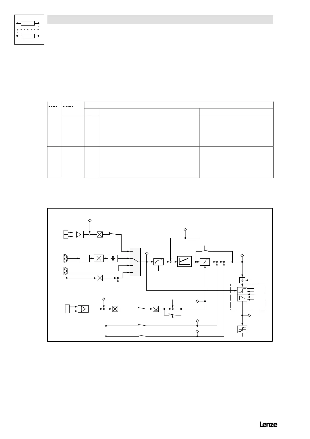
7.6.2 Speed dependent armature current limitation
4900Str078
-
+
2
1
C 047
C 050
+
C 051
40
42
43
41
+
C 145/C 146
C 025/C 027
3
4
±180 V
C27 C28
C 25/C 26
C 025/C 027
-
AB
QSP
C 070 V
C 071 T
C 072 K
pn
nn
dn
C 056
C 063
C 022, C 023
C310
C311
C312
C313
C314
C 025/C 026
C 025/C 026
C 025/C 027
C 145/C 146
++
C 148
C 149
C 146/C 147
C 146/C 147
+
-
100 %
C 282
C 198
n
set
a t n -c o n tro lle r
in % o f n
max
n
act
n
o ffs e t
Tacho
Increm ental
encoder
Resolver
I
act
V
arm ature voltage
C232
I · R - com pensation
0 V = no torque
10 V = m ax. torque
External torque lim it
C 005 C onfiguration
n-controller
M
set
in %
o f M
max
I
set
I
max
I
Fact
Additional torque setpoint 1
Additional tor
ue set
o in t 2
speed-dependent
c u r r e n t lim ita tio n
Enc.
const.
FIG 7-51 Signal-flow chart (section) for speed-dependent armature current limitation
Purpose
If DC machines are drive with rated armature current in field weakening operation,
the segment voltage (at the armature) can reach impermissibly high values.