Installation
4-13
48XX/49XXSHB0399
4.3.4 Control connections
15
96
15
96
15
96
15
96
15
96
X9
X6 X7
X8
X5
X4
X2
X3
X1
18
915
X11
18
915
X10
V1 V2
12345678910
40 41 44 45K11K14A1 A2 A3 A4
20 21 22 28 E1 E2 E3 E4 E5 39
A5 59 60 61 62 63 80VE990 FE
4900Str008
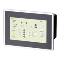
FIG 4-8 Control connections for the controller
X1 - X4 Control terminals
X5 Digital frequency/incremental encoder input (Dig_In_1)
X6 LECOM1 interface (RS 232 / 485)
X7 Resolver connection
X8 Digital frequency output
X9 Digital frequency/incremental encoder input (Dig_In_2)
X10, X11 Fieldbus connnections (as option e.g. 2110 for InterBus)
V1, V2 Displays for fieldbus options (option)
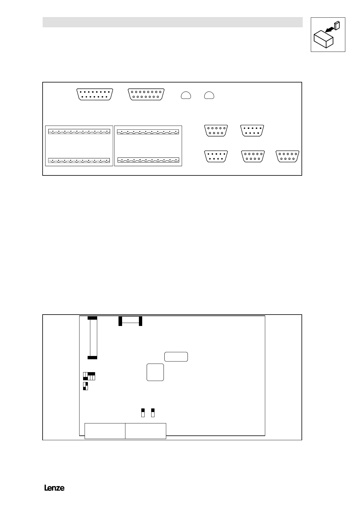
Switch on the control module
Some function of inputs and outputs can be changed via the switches on the
control module 4902MP. For settings ensure
- that no voltage is applied
- the cover is removed (4 mounting screws)
S4
S3
S1 S2
X4
X1
X2A X2B
4902MP.xx.xx
on
on
onon
4900Str009
FIG 4-9 Positions of switches S1 to S4 on the control module

 Loading...