Installation
4-30
48XX/49XXSHB0399
4.4.2 Components of the CE-typical drive system
System component Specification
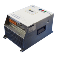
Controller 4800/4900 DC controllers
RFI filter For data and filters see chapter 13.4
Mains choke For assignment and technical data see chapter 13.2
Armature and field cable Unscreened power cable
Rated max. length: 50m
Control cables Screened signal cable type LIYCY
Encoder cable for digital frequency Lenze system cable or screened signal cable, twisted in pairs, tin plated E-CU braid
with 75% optical overlay
Encoder cable for resolver Lenze system cable type EWLR or screened signal cable, twisted in pairs, tin plated
E-CU braid with 75% optical overlay
Motor Separately excited DC motor
Lenze series MGFQ, MGFR or similar
Accessories InterBus module 2110IB
Profibus module 2130IB
Controller, RFI filter and mains choke are mounted on the same assembly board
inside a standard control cabinet.
4.4.3 Measures required
Control cabinet assembly board
( For HF grounding, only use mounting plates with an excellent conductive
surface (e.g. zinc-coated surface).
( If you use mounting plates with badly conductive surfaces (e.g. painted,
anodized, yellow passivated):
- Remove the paint or coating from the contact surface of the mains filters,
controllers, and screen connections, to provide a large and conductive
connection.
( When using several mounting plates, connect them with a surface as large
as possible (e.g. using copper bands).
( Connect the controller, RFI filter and mains choke to the grounded
mounting plate with a surface as large as possible.
Power connection
( Avoid unnecessarily long cables
( Ensure the separation of motor cable and signal or mains cable.
( Ensure separation of unscreened and screened cables (distance > filter
length)
( Ensureadistanceasshortaspossiblebetweentheconductors
(single- c ores)
( Both ends of unused cores should be connected to ground/PE.

 Loading...