Configuration
7-1
48XX/49XXSHB0399
7 Configuration
7.1 Speed controlled operation
For standard applications, the drive can be immediately commissioned with the
default settings. To adapt the drive to special requirements, please observe the
notes in the following chapters.
7.1.1 Set-valueselection
4900Str028
-
+
+
-
2
1
100 %
C 047
JO G 1
JO G 2
JO G x
E4 E5
0
1
±1
21 22
QSP
Ex
Ex
C 134QSP
C 012 T
C 013 T
ir
if
C 190
E3
0
1
6
-10 V ... +10 V
+
8
-10 V ... +10 V
+
C 105
SW I
C 220, C 221
QSP
n
n
max
C 046
C 011
C 145/C 146
C 025/C 026
offset
n
offset
n
C 049
C 145/C 146
C 025/C 027
C 025/C 027
C 050
max
+
C 051
n
10
12
13
11
+
offset
n
Tacho
C 145/C 146
C 025/C 027
3
4
±180 V
C 027 C 028C025/C026
Resolver
C 025/C 027
-
I
AB
QSP
n-controller
C 070 V
C 071 T
C 072 K
pn
nn
dn
C 056
M in %
of M
max
C 063
I
I
max
C 022, C 023
I
C310
C311
C312
C313
C314
C 042
in % o f n
max
C 025/C 026
C 025/C 026
C 025/C 026
C 025/C 027
C 145/C 146
n
set'
/-
·+
C46
100% - C 49
C 286 C 287
set
CW CCW
Enable
RFG zero
set
Additional
setpoint
n at n-controller
in % o f n
Enc.
const.
Increm ental
encoder
0 V = no reduction
1 0 V = m a x . re d u c tio n
C 0 0 5 C o n fig u ra tio n
set
Fact
Main si
nal
ath
Configuration C005 = -1x-
RFG stop
V
A rm a tu re v o lta g e
C 232
I · R - com pensation
Torque reduction
C 041
CW /CCW
act
set
Z o ff
set
act
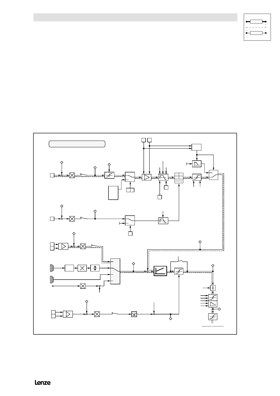
FIG 7-1 Signal-flow chart showing the set-value processing for speed control with addition setpoint
(C005 = -1X-) default setting

 Loading...