9300 Servo PLC
System blocks
2.5 ANALOG1_IO
2-16
L
ServoPLC EN 2.0
2.5 ANALOG1_IO
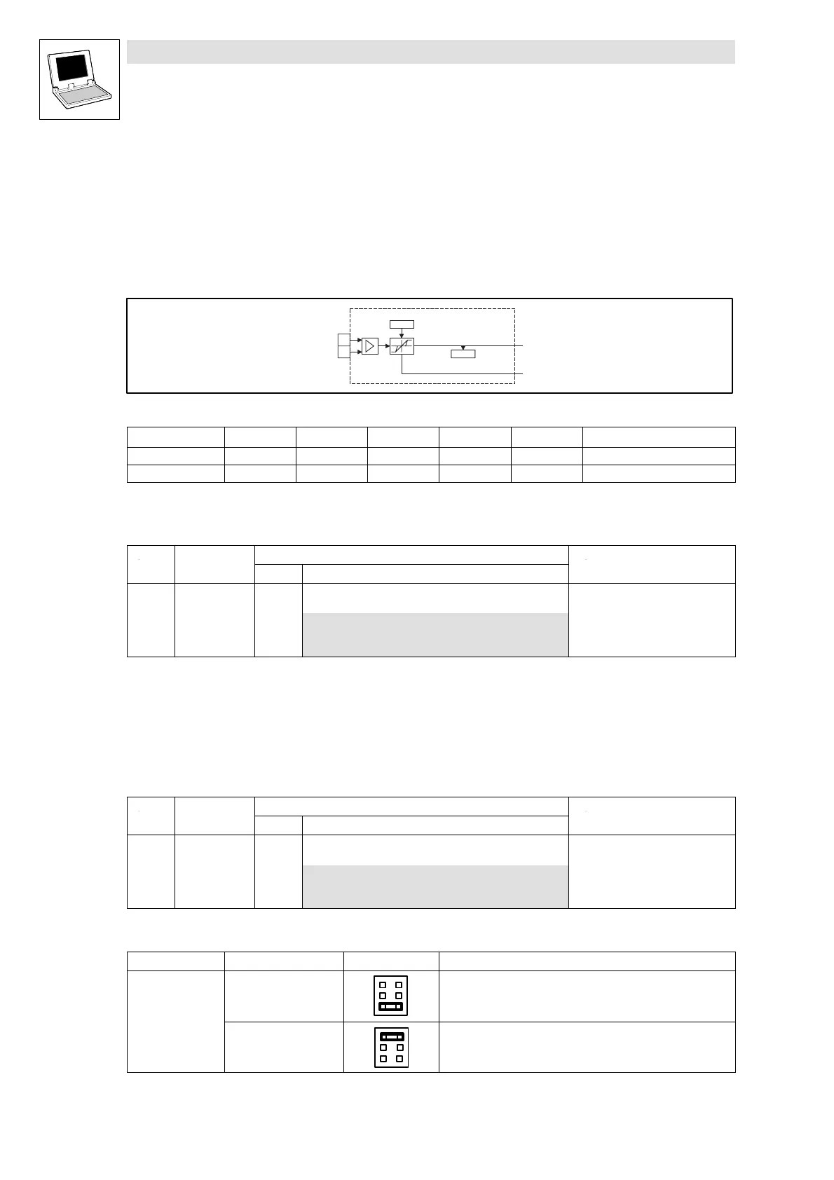
2.5.1 Inputs_ANALOG1
Analog input 1 (module number 11)
This SB forms the interface for analog difference signals via terminal X6/1, 2 as setpoint input or
actual value input.
Inputs_ANALOG1
AIN1_nIn_a
C0400
AIN1_bError_b
1
2
C0034
X6
Fig. 2-8 Inputs_ANALOG1
VariableName
DataType SignalType Address DIS DIS format Note
AIN1_nIn_a Integer analog %IW11.0 C0400 dec [%] Analog input 1
AIN1_bError_b Bool binary %IX11.1.0 - - TRUE, if I <2mA
Master voltage/current selection
• Use C0034 to set whether the input is to be used for a master voltage or a master current:
Code LCD
Possible settings
Info
Lenze Selection
C0034 Mst current 0 Selection: Master voltage/master
current
0 -10 V ... + 10 V (master voltage)
1 +4mA...+20mA (mastercurrent)
2 -20 mA ... +20 mA
• Please see the jumper position X3 at the front of the 9300 Servo PLC (terminal assignment).
Use as 4 ... 20 mA master current input
• If the input is used as master current input (C0034 =1),
•
AIN1_bError_b
= TRUE if the master current is < 2 mA, otherwise it is FALSE.
• Use C0598 to set the reaction to a master current < 2 mA:
Code LCD
Possible settings
Info
Lenze Selection
C0598 MONIT SD5 3 Configuration monitoring:
Master current at X6/1, 2 < 2 mA
0TRIP
2 Warning
3Off
Terminal assignment
Terminal Use Jumper X3 Data
X6/1, 2
Difference input
Master voltage
6
4
2
5
3
1
Level:
Resolution:
Normalisation:
-10V...+10V
5 mV (11 bit + sign)
±10 V ≡±16384 ≡±100 %
Difference input
Master current
6
4
2
5
3
1
Level:
Resolution:
Normalisation:
-20mA...+20mA
20 µA (10 bit + sign)
±20 mA ≡±16384 ≡±100 %
efesotomasyon.com - Lenze
 Loading...


