9300 Servo PLC
Preface and general information
1-3
L
ServoPLC EN 2.0
1.2 System block introduction
For a long time, Lenze has followed the principle of describing inverter functions with the aid of
function blocks (FB’s). This principle can also be found in the IEC1131-3 standard.
• Functions which can be used as software functions in projects are stored in function libraries
as function blocks or functions. Required SBs must be explicitely linked to the project via
the control configuration of DDS.
• In addition, quasi-hardware functions are available, as system blocks (SBs).
1.2.1 System block principle
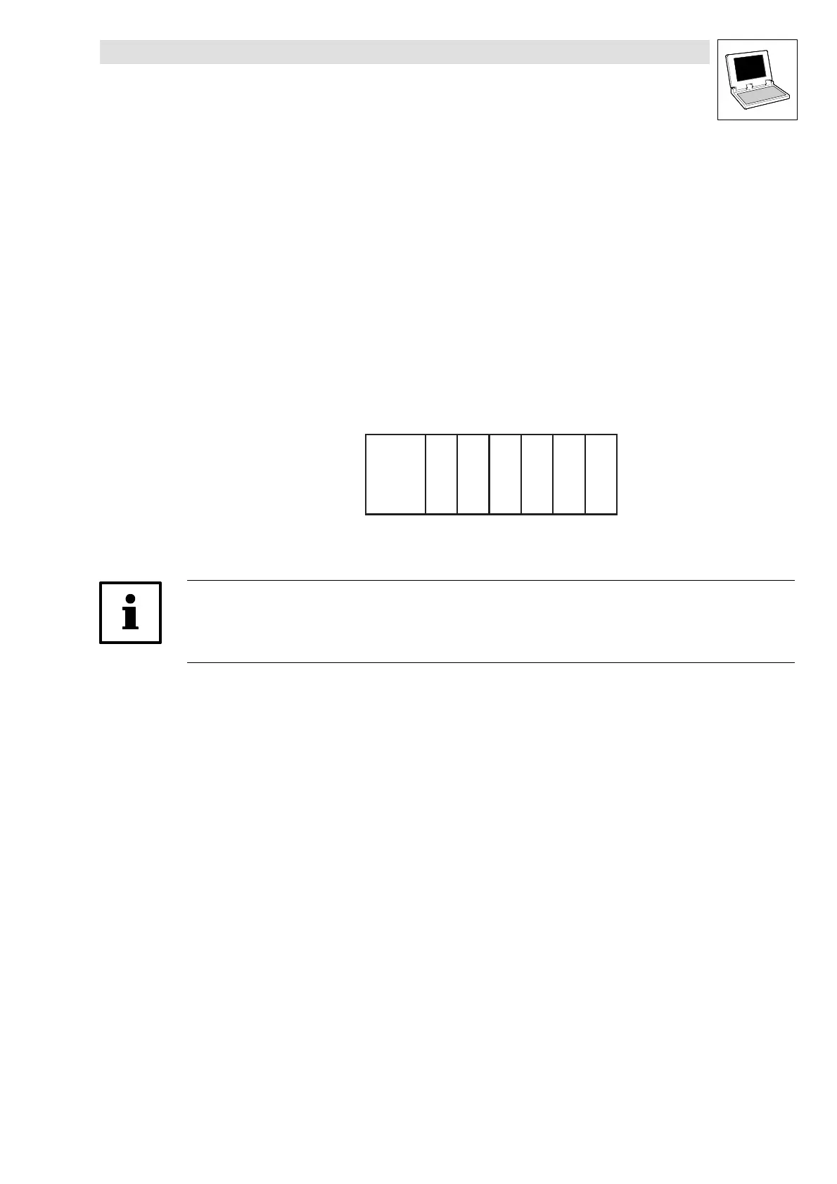
The system-block principle can be explained by means of a PLC system in a rack:
• The rack contains the CPU, digital I/Os, analog I/Os, counter card, positioning card, etc. as
additional cards:
CPU
xxxxxx
x = Additional cards
• The CPU can directly access the additional cards, and process the resulting information.
• Additional cards have fixed addresses for access.
With Lenze PLCs, system blocks can be compared with these additional cards!
System blocks are special (hardware) function blocks permanently integrated into the
run-time system of the PLC.
• SBs can address real hardware.
• SB are assigned/identified through so-called module numbers. (^ 1-4)
• SB inputs and outputs are accessed via system variables or absolute memory addresses.
(^ 1-5)
• Inputs/outputs are always classified from the program’s point of view. (^ 1-6)
• Required SBs must be explicitely linked to the project via the control configuration of DDS.
(^ 1-7)
efesotomasyon.com - Lenze
 Loading...


