EasyManua.ls Logo

Lenze Global Drive 9300 Servo PLC Series User Manual

Lenze Global Drive 9300 Servo PLC Series
130 pages
To Next Page IconTo Next Page
To Previous Page IconTo Previous Page
Page #64 background imageLoading...
Page #64 background image
9300 Servo PLC
System blocks
2.12 MCTRL_MotorControl
2-50
L
ServoPLC EN 2.0
2.12.14 Feedback system
Use the following codes to configure the feedback system for the position controller and speed
controller:
Code LCD
Possible settings
IMPORTANT
o
Lenze Selection
[C0420] Encoder const 512 Encoder: Constant for encoder input
X8
1 {1 inc/rev} 8192
[C0490] Feedback pos 0 Feedback system for the speed con-
troller
C0490 = 0, 1, 2 can be mixed
with
C0495 = 0, 1, 2.
C0490 = 3, 4 sets C0495 to the
same value.
0 Resolver at X7
1 Encoder TTL at X8
2 sin/cos encoder at X8
3 Absolute value encoder ST at X8
4 Absolute value encoder MT at X8
[C0495] Feedback n Feedback system for the speed con-
troller
C0495 = 0, 1, 2 can be mixed
with
C0490 = 0, 1, 2.
C0495 = 3, 4 sets C0490 to the
same value.
0 Resolver at X7
1 Encoder TTL at X8
2 sin/cos encoder at X8
3 Absolute value encoder ST (single turn) at X8
4 Absolute value encoder MT (multi turn) at X8
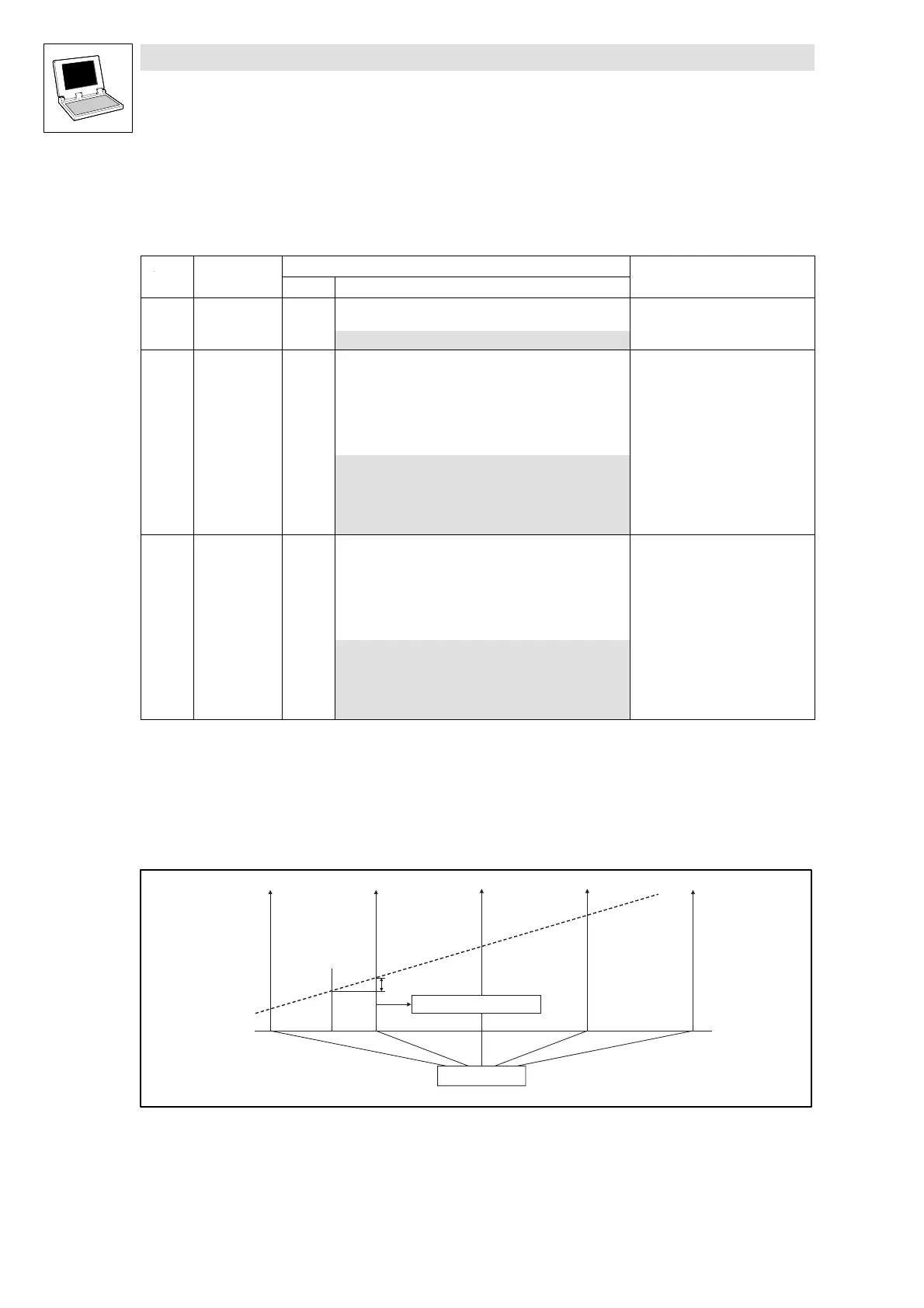
2.12.15 Touch probe (TP)
Process: The current angle value (digital frequency input value) is stored by a quick interrupt in the
operating system when a signal change occurs at the TP activating input (e.g. X5/E4).
MCTRL_dnActIncLastScan_p
TP
j
Fig. 2-25 Function diagram of a TP
Time-equidistant start of an interval-task
ϕ Phase-angle signal
efesotomasyon.com - Lenze
Show/Hide Bookmarks

Table of Contents

Other manuals for Lenze Global Drive 9300 Servo PLC Series

Questions and Answers:

Lenze Global Drive 9300 Servo PLC Series Specifications

General IconGeneral
BrandLenze
ModelGlobal Drive 9300 Servo PLC Series
CategoryDC Drives
LanguageEnglish

Summary

1 Preface and general information

1.2 System block introduction

Explains the principle and structure of system blocks (SBs) in Lenze PLCs.

2 System blocks

2.1 AIF1_IO_AutomationInterface

Interface for input/output signals from attached fieldbus modules.

2.7 DCTRL_DriveControl

Controls the Servo PLC for states like TRIP, QSP, or controller inhibit.

2.12 MCTRL_MotorControl

Contains control functions for drive machine: phase, speed, motor control.

2.12.17 Monitoring

Covers monitoring functions for drive protection against impermissible conditions.

3 Appendix

3.1 PLC functionality

Details the PLC's input/output capabilities, memory, and processing.

3.3 System error message

Provides an overview of system error sources, meanings, and possible responses.

3.3.2 Cause and remedy

Lists causes and remedies for various system error messages.

3.4 Code table

Reference table for codes used in parameter settings and configuration.

Related product manuals