9300 Servo PLC
System blocks
2.12 MCTRL_MotorControl
2-54
L
ServoPLC EN 2.0
2.12.17 Monitoring
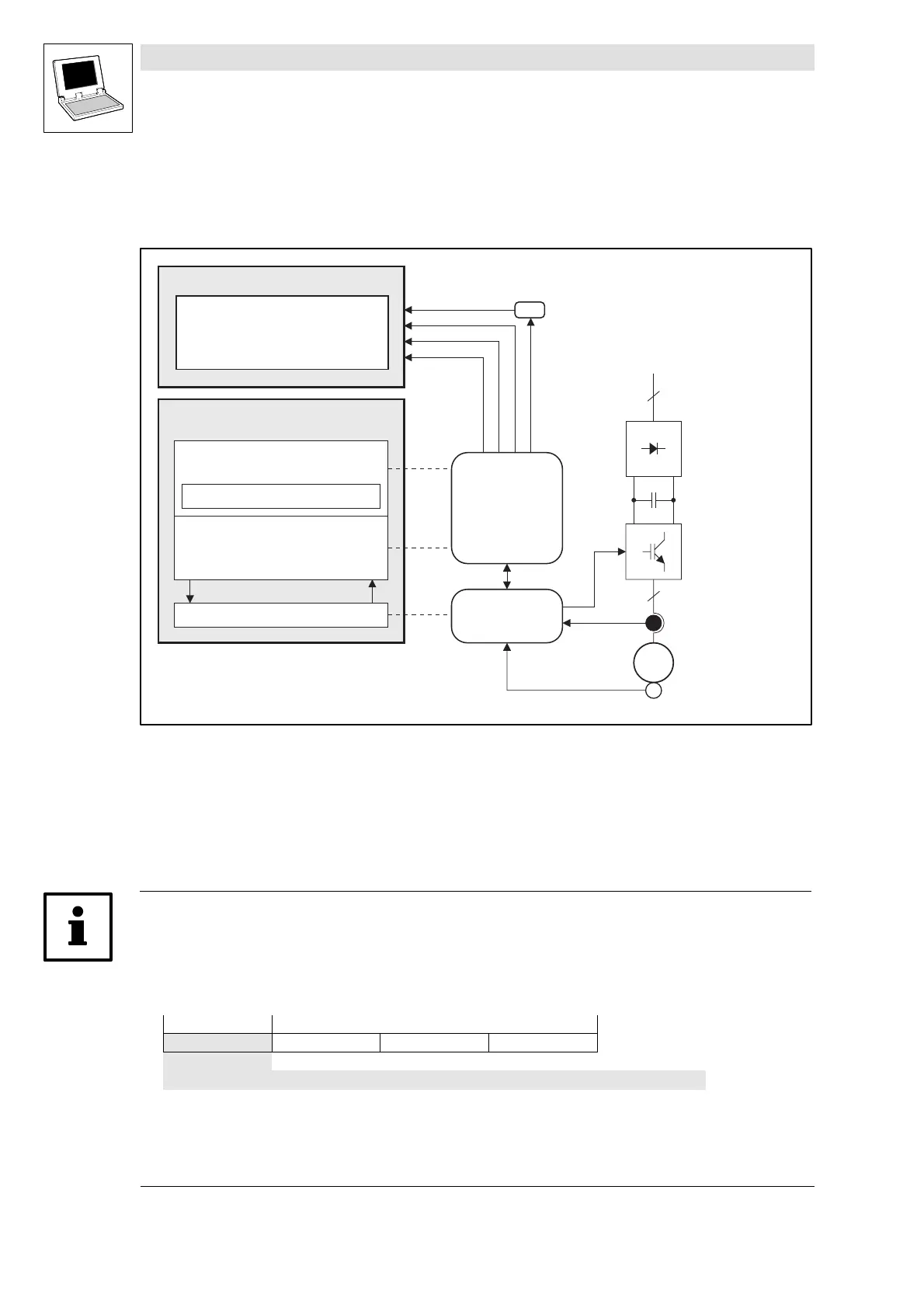
The 9300 Servo PLC comprises two independent sectors, the motor control and the PLC.
3
3~
DSP
Digital Signal Processor
Controller
CAN
3
PLC program
(to IEC1131-3, changeable)
Technology functions
Operating system
Drive control
Communication
Motor control
Memory
(FLASH, EEPROM, RAM)
Interfaces
System bus (CAN)
Feldbuses
Digital frequency
Analog/digital I/O
Rectifier
Inverter
Asynchronous motor
Standard motor
Synchronous motor
with resolver/encoder
SIN/COS encoder
The motor control includes several monitoring function which protect the drive from impermissible
operating conditions.
• If a monitoring function is activated, the drive will respond accordingly and a system variable
will be set TRUE as long as the monitoring function is being active.
• The system variables of the monitoring functions can be processed by the user program of the
PLC.
Tip!
• The current error number is also displayed in the variable
DCTRL_wFaultNumber
.
• The history buffer (C0168/x) stores system error messages with an offset which indicates the
type of response:
Type of response No. of system error message
0 ... 4 x x x
0-TRIP 1 - Message 2-Warning 3-Off 4 - Error/QSP
• More information about the error sources detected by the PLC and remedies can be found in
chapter 3.3.
(^ 3-3)
• In general, faults do not affect the serviceability of the PLC!
efesotomasyon.com - Lenze
 Loading...


