3. Product Overview HDMI-3D-OPT series – User's Manual 14
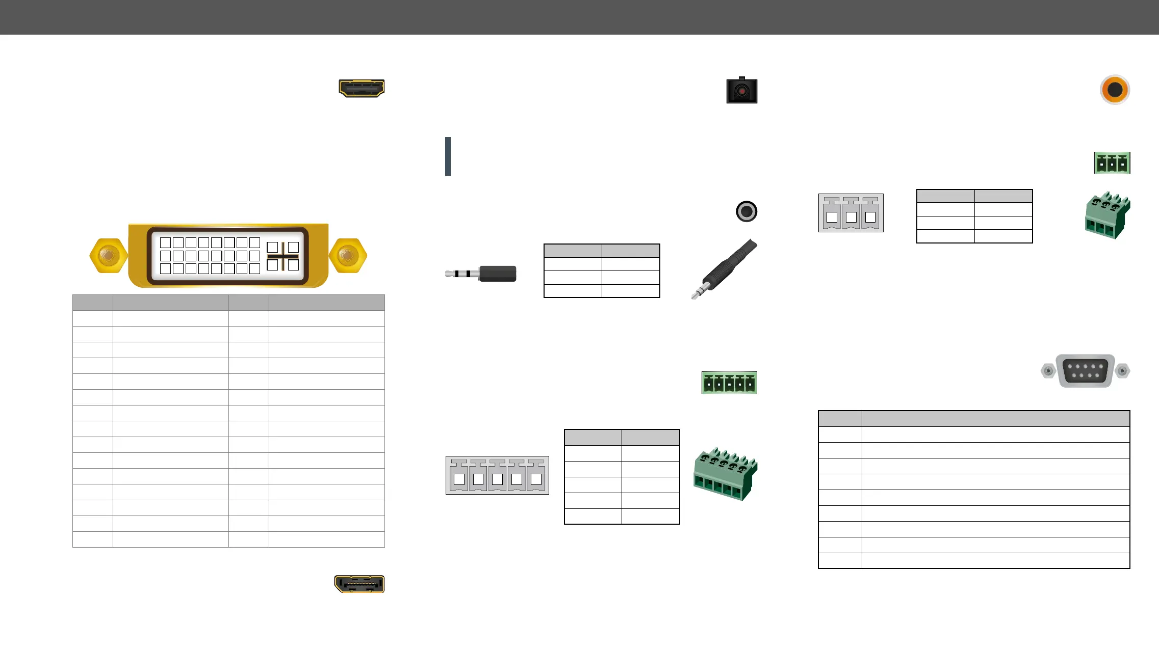
HDMI Connector
The extenders provide standard 19-pole HDMI connector
for input and output. Always use high-quality HDMI cable
for connecting sources and displays.
DVI-I Connector
Dual-Link connectors (only digital pins are internally connected) for
processed.
Pin Signal Pin Signal
1 TMDS Data2- 16 Hot Plug Detect
2 TMDS Data2+ 17 TMDS Data0-
3 TMDS Data2 Shield 18 TMDS Data0+
4 Not connected 19 TMDS Data0 Shield
5 Not connected 20 Not connected
6 DDC Clock 21 Not connected
7 DDC Data 22 TMDS Clock Shield
8 Not connected 23 TMDS Clock+
9 TMDS Data1- 24 TMDS Clock-
10 TMDS Data1+ C1 Not connected
11 TMDS Data1 Shield C2 Not connected
12 Not connected C3 Not connected
13 Not connected C4 Not connected
14 C5 GND
15
DisplayPort Connector
pole DisplayPort connector for input. Always use high
quality DP cable for connecting DisplayPort devices.
1 2 3 4 5 6 7 8
9 10 11 12 13 14 15 16
C1 C2
C4C3
C5
17 18 19 20 21 22 23 24
HDMI-3D-OPT series transmitters and receivers provide
Maximum Fiber
Cable Extensions section.
connector if the cable is connected to the transmitter only and the
laser is active.
The connector is used for receiving unbalanced analog audio
phone jack, phone plug and mini-jack plug.
Pin nr. Signal
1 Left
2 Right
3 Ground
Jack audio plug pin assignments
Audio
Interface section.
audio output. Unbalanced audio signals can be
connected as well. For unbalanced output connect + and ground to
the source and connect – to the ground.
Pin nr. Signal
1 Left+
2 Left-
3 Ground
4 Right-
Right+
Analog audio connector and plug pin assignments
Compatible Plug Type
Phoenix
®
Audio Interface section. Audio cable wiring guide is in the Audio Cable
section.
1 2 3 4 5
receptacles for digital coaxial audio outputs.
Audio
Interface section.
The extender contains a 3-pole Phoenix connector which is
used for RS-232 serial connection.
Pin nr. Signal
1 Ground
2
3
RS-232 connector pin assignments
Compatible Plug Type
Phoenix
®
Serial
Interface section.
RS-232 port which can be connected by
an industry standard 9-pole D-sub female
connector.
Pin nr. RS-232 pin-out
1 Not connected
2
3
4 DTR (Internally connected to Pin 6)
5
6 DSR (Internally connected to Pin 4)
7 RTS (Internally connected to Pin 8)
8 CTS (Internally connected to Pin 7)
9 Not connected
Serial
Interface section.
1 2 3
1
5
9 6
 Loading...