3. Product Overview HDMI-3D-OPT series – User's Manual 20
USB KVM - Example 2
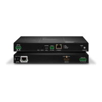
The Concept
Two devices are connected to the USB ports of the Receiver:
▪ A Drawing table;
▪ A USB HUB which has four USB ports - a Keyboard and a Mouse are connected to the HUB.
The PC can be controlled by the keyboard and the mouse, as well as the drawing table is also working as an
input device beside of them.
Settings:
▪ Keyboard and mouse (via the USB HUB): the devices need to be set to Composite mode. The extenders can
▪ Drawing table: the device needs to be set to Transparent mode because this kind of devices may have
special functions which cannot be supported by the composite mode.
All related settings are available in the LDC software, see the section.
INFO: The extenders support up to 8 physical USB HUB ports.
The interfaces of the HDMI-3D-OPT series extenders can be used to install the device at various point of a
section is about to present the possibilities through the control ports built-in the the extenders.
Serial Interface
receiver have RS-232 interface.
Technical Background
Serial data communication can be established via the local RS-232 port (Phoenix connector) or via the optical
the Baud rates are different, the microcontroller does the conversion automatically between the ports). The
RS-232 port can be switched to Control mode, Command Injection mode, or can be Pass-through mode; see
HDMI-3D-OPT-RX150RA
receiver
HDMI-3D-OPT series
transmitter
FIBER OPTICALUSB USB
USB
POWER
HDCP
RS-232
FUNC.
USB
CONT.
HDMI
SIGNAL
LASER
HOTPLUG
EMULATE
USB LINK
FIBER LINK
Keyboard and Mouse
PC
:
:
1 4
5
3
2
USB
Autoselect
SHOW
ME
AUDIO
SELECT
VIDEO
SELECT
VIDEO VIDEO VIDEOAUDIO AUDIO AUDIO VIDEO
AUDIO
HDCP AUDIO1
DP IN DVI-D IN
RST
AUDIO2
AUDIO1 IN
HDMI2 INHDMI1 IN
USB HUB
Drawing table
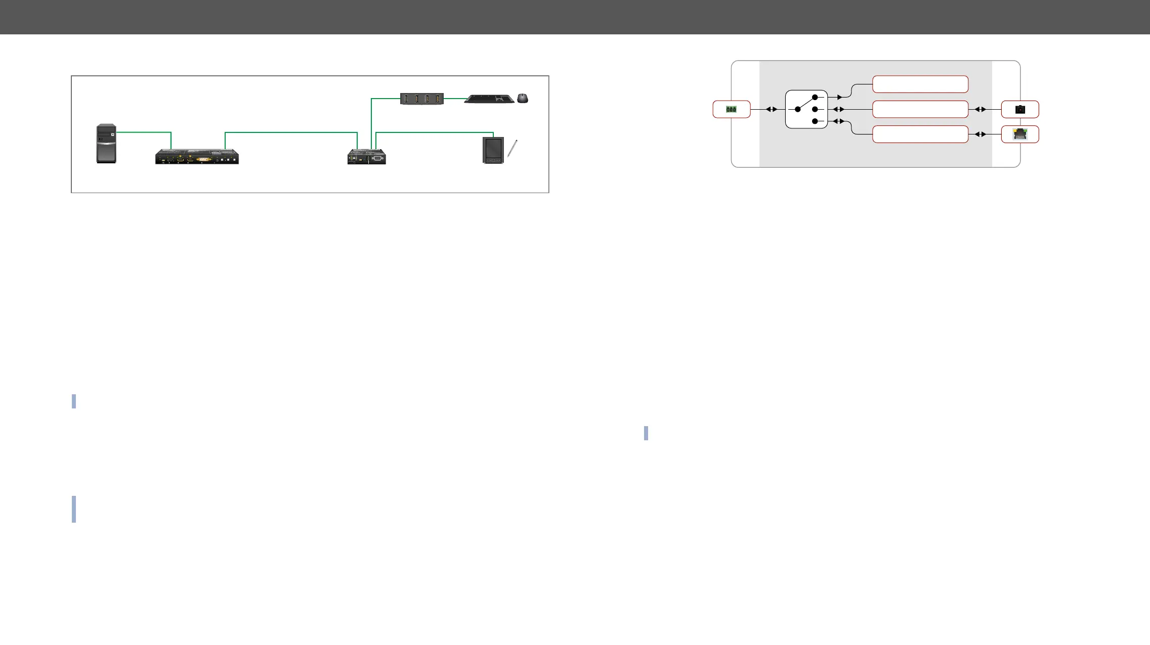
The block diagram of the serial interface
1
The Local serial port is in Control mode.
2
The Local serial port is in Pass-through mode.
3
The Local serial port is in Command Injection mode.
All settings are available in the LDC software, see settings in the RS-232 section.
Control Mode
The incoming data from the given port is processed and interpreted by the CPU. The mode allows to control
Pass-through Mode
In pass-through mode, the given device forwards the data that is coming from one of its ports to another
same type of port. The command is not processed by the CPU. Incomming serial data is forwarded from one
port to another port inside the extender.
Command Injection Mode
and local) for this purpose. E.g. the default Command Injection port number of the local RS-232 port is 8001.
If data is coming from the optical interface which addresses to the port no. 8001, it will be transmitted to
the Tx pin of the local RS-232 port. That also works in the opposite direction of course and the method is the
same on the serial interface of the optical port as well.
Mode switch
out
RS-232 / OPT converter
RS-232 / TCP converter
Device control (local serial)
Ethernet
CPU
1
2
3
 Loading...