Faults
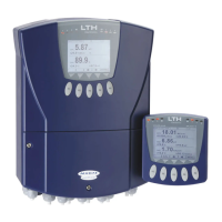
MXD70 Suspended Solids / Turbidity
Setup and Operating Guide
- 45 -
Faults
Fault Finding
NOTE: THERE ARE NO USER SERVICEABLE PARTS INSIDE THE UNIT
The MXD70 Series has been designed to include a wide range of self diagnostic tests, some of which
are performed at switch on, and some on a continuous basis. This guide aims to provide a route to
diagnosing and correcting any faults that may occur during normal operation. The table shown
previously in this section gives a list that the MXD70 series generates, along with their probable causes.
If after these checks the fault has not been cleared contact LTH. Please have as much of the following
information available as possible in any communication with LTH, to enable quick diagnosis and
correction of the problem.
Serial number of the instrument, input and output cards.
The approximate date of purchase.
The software version number.
Details of the program settings and application.
Electrical environment and supply details.
Circumstances under which the fault occurred.
The nature of the fault or faults.
Any error messages that are displayed.
The transmitter type, cable length and type.
Current output configuration.
Relay connection configuration.
It is often worthwhile to check the measurement by an independent method, for example using a
handheld meter.
The Instrument Appears Dead
Check that power is available to the unit. Using a voltmeter, set to AC or DC, check the power supply
voltage at the connector. The design of the MXD70 Series allows the unit to accept from 85 to 250V AC
or DC; an alternative option allows operation from 18 to 32V AC or DC, check the connection label for
voltage specification. Check that the power cable is securely and correctly attached. There are no user
serviceable fuses fitted within this unit.
The Access Code Does Not Work
It is probable that the access code has either been changed or the operator does not recall the code
correctly. Contact LTH or your local distributor should this problem arise.
The Input Reading Is Constantly Over-range, Under-range or Incorrect
Ensure that the probe input is correctly connected (see Installation Section) and that the transmitter
is not faulty or damaged.
Check that linearisation curve has been correctly entered within the Channel Setup menu (see page
14).
Check the probe for fouling or damage.
Check the raw probe signal reading in a high and low sample. If the probe signal is not reading as
expected contact a service engineer for guidance.
Try resetting the offset and slope calibration (see page 22) and re-calibrate the probe in high and
low samples.
Where extension cables have been used, try connecting the sensor directly to the instrument.
 Loading...
