9 Visualization
Maschinenfabrik Reinhausen GmbH 2020296 6385142/08 ENETOS
®
ED
Property Options
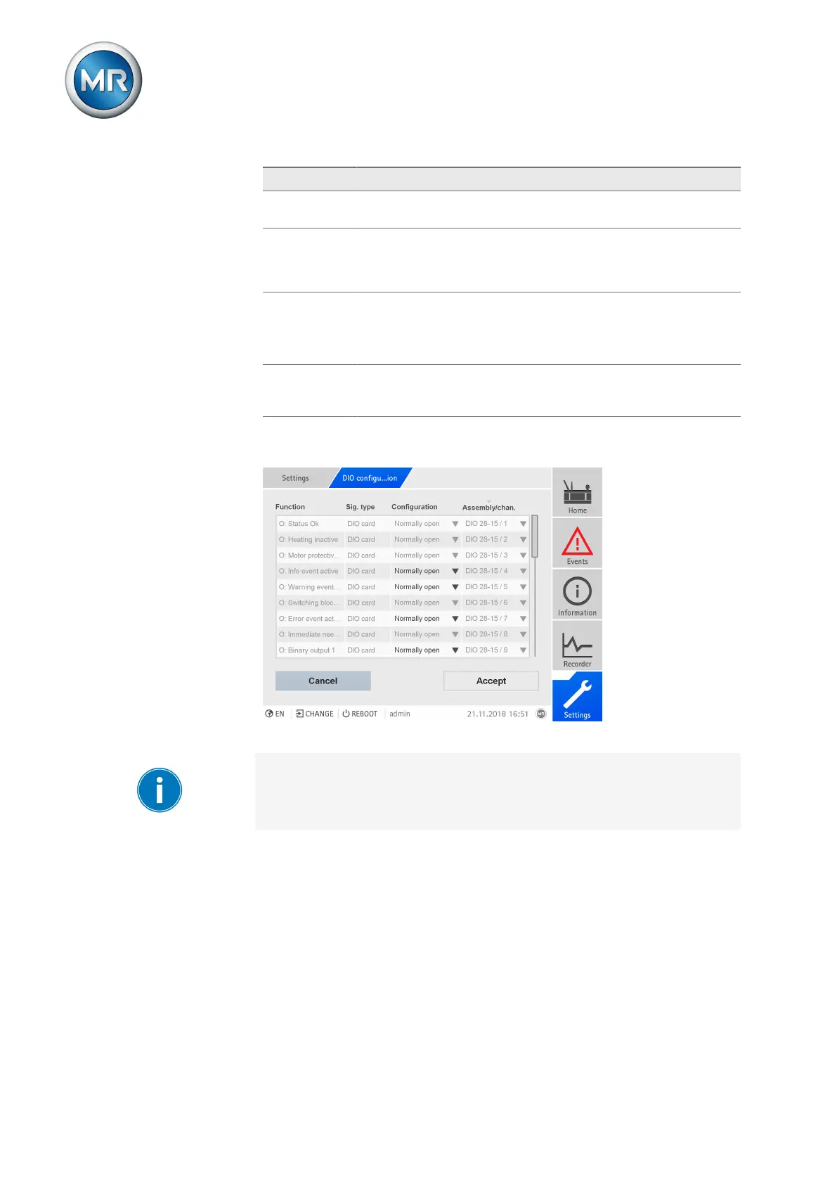
Function Function of the digital input (I: ...) or the digital output (O: ...). You
can adjust the designation.
Signal type Select signal type:
▪ Digital: Digital input
▪ Modbus (MR sensor bus)
Configuration
1)
DI: High active or low active
DO: N/O contact (NO), N/C contact (NC); Note: If the device is dis-
connected or in the event of an error, the digital outputs are always
open (no bi-stable relay).
Assembly/
channel
1)
Channel of the DIO assembly to which the function is linked. Func-
tions that are not linked with a channel are identified with "-". Note
the connection diagram supplied.
Table90: Configuration of the digital inputs and outputs
1)
Not available with sensors connected over the MR sensor bus (Modbus).
Figure223: Configuring digital inputs and outputs
The operation described below is only possible if you access the visualiza-
tion using a computer. You can only change the configuration of the digital
inputs and outputs if you have a Parameter Configurator or Administrator
role.
When in delivery status, you can log in as the administrator as follows:
▪ User name: admin
▪ Password: admin
Creating a backup You need to create a backup to be able to reset the system in the event that
any incorrect configuration settings are made. To do so, proceed as follows:
1. Go to Settings > Export.
2. Go to the option Settings to export a backup copy of the current settings.
3. Select the desired Interface (USB or PC).
 Loading...