10
4.2) Programming methods
Just the two P1 and P2 buttons on the card are used for all
programming phases
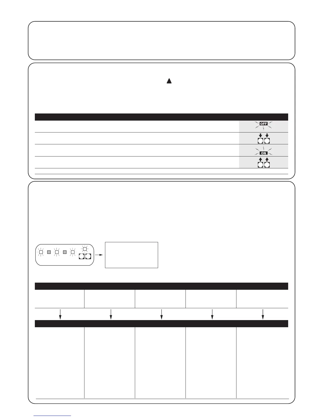
In this case, the 5 “INPUT” Leds normally indicating the status of the
inputs show the selected “parameter”.
Example:
There are two different programming levels:
• At level 1, the functions can be activated or deactivated. Each
INPUT Led corresponds to a function: if the Led is on, the function
is active; if it is off, it is deactivated.
Led 1 : “Automatic” function
Led 2 : “Condominium” function
Led 3 : Pre-flashing
Led 4 : Close after photo
Led 5 : Opening delay
• It is possible to switch from level 1 to level 2 where the function
parameters can be chosen, each Led corresponds to a different
value to associate with the parameter.
4.1) Delete memory
Each new programme replaces the previous settings, normally it is
not necessary to “delete all” the memory.
If required, the memory can be totally deleted by performing this
simple operation:
After deleting the memory, a new search must be
made for the mechanical stops, while all the functions
return to their pre-set values.
Level 1:
Led 1 Led 2 Led 3 Led 4 Led 5
“Automatic”“Condominium” Pre-flashing Close 4 seconds Opening delay
function function after photo
Level 2:
Parameter: Parameter: Parameter: Parameter: Parameter:
Pause time AUX input Pre-flashing time Current Delay
sensitivity
L
ed 1 : 5s Led 1 : Type 1 partial opening Led 1 : 2s Led 1 : Level 1 Led 1 : 2s
Led 2 : 10s Led 2 : Type 2 partial opening Led 2 : 4s Led 2 : Level 2 Led 2 : 4s
Led 3 : 20s Led 3 : Open only Led 3 : 6s Led 3 : Level 3 Led 3 : 6s
Led 4 : 40s Led 4 : Close only Led 4 : 8s Led 4 : Level 4 Led 4 : 8s
Led 5 : 80s Led 5 : Photo 2 Led 5 : 10s Led 5 : Level 5 Led 5 : 10s
Leds off: Leds off:
input disabled current sensitivity disabled
Level 1 = most sensitive
Level 5 = least sensitive
All the functions described in the “Programmable functions” chapter
can be selected by means of a programming phase which
terminates by memorising the choices made.
The control unit therefore has a memory which stores the functions
and parameters relative to the automation process.
4) Programming
3s
Table “A1” Delete memory: Example
1. Disconnect the power supply
2. Press and hold down buttons P1 and P2 on the card
3. Connect the power supply
4. Wait for at least 3 seconds before releasing the two keys
N.B.: if the memory was deleted correctly, all the Leds will switch off for 1 second.