The PHOTOTEST function is a standard feature on the A400
control unit. This is an excellent solution as regards the reliability of
safety devices and puts the control unit and safety devices into
“category 2” as per UNI EN 954-1 standard (ed. 12/1998).
Whenever a manoeuvre is begun, the relative safety devices are
checked and only if everything is in order will the manoeuvre start. All
this is only possible if a special configuration of the safety device
connections is used; in practice, the “TX” photocell transmitters are
powered separately from the “RX” receivers.
The SYNCHRONISM function (available on all NICE photocells) is the
only way of ensuring that two pairs of photocells do not interfere with
each other.
The inputs subject to the phototest procedure are PHOTO, PHOTO1 and
the AUX input if configured as PHOTO2. The Phototest phase takes place at
the beginning of each manoeuvre and cannot be disabled; therefore, if one of
these inputs is not used, it must be connected to terminal n°13, please
consult the following figures for examples of connections.
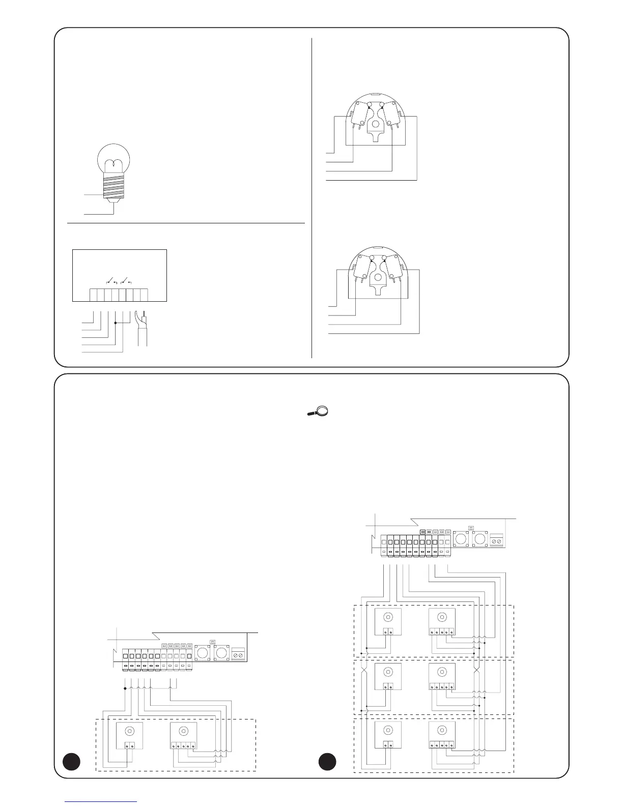
2.4.4) Phototest
Slow flashing means the gate is
opening.
Fast flashing means the gate is
closing
Lamp permanently on means the
gate is open.
Photo, photo1 and photo2 connection diagram.
Connection diagram with just the PHOTO photocell
Example 1
How to connect the switch in
order to perform the STEP-BY-
STEP and STOP functions.
Example 2
How to connect the switch in
order to perform the STEP-BY-
STEP function and one of the
auxiliary input functions
(PEDESTRIAN, OPEN ONLY,
CLOSE ONLY…).
 Loading...