7
GB
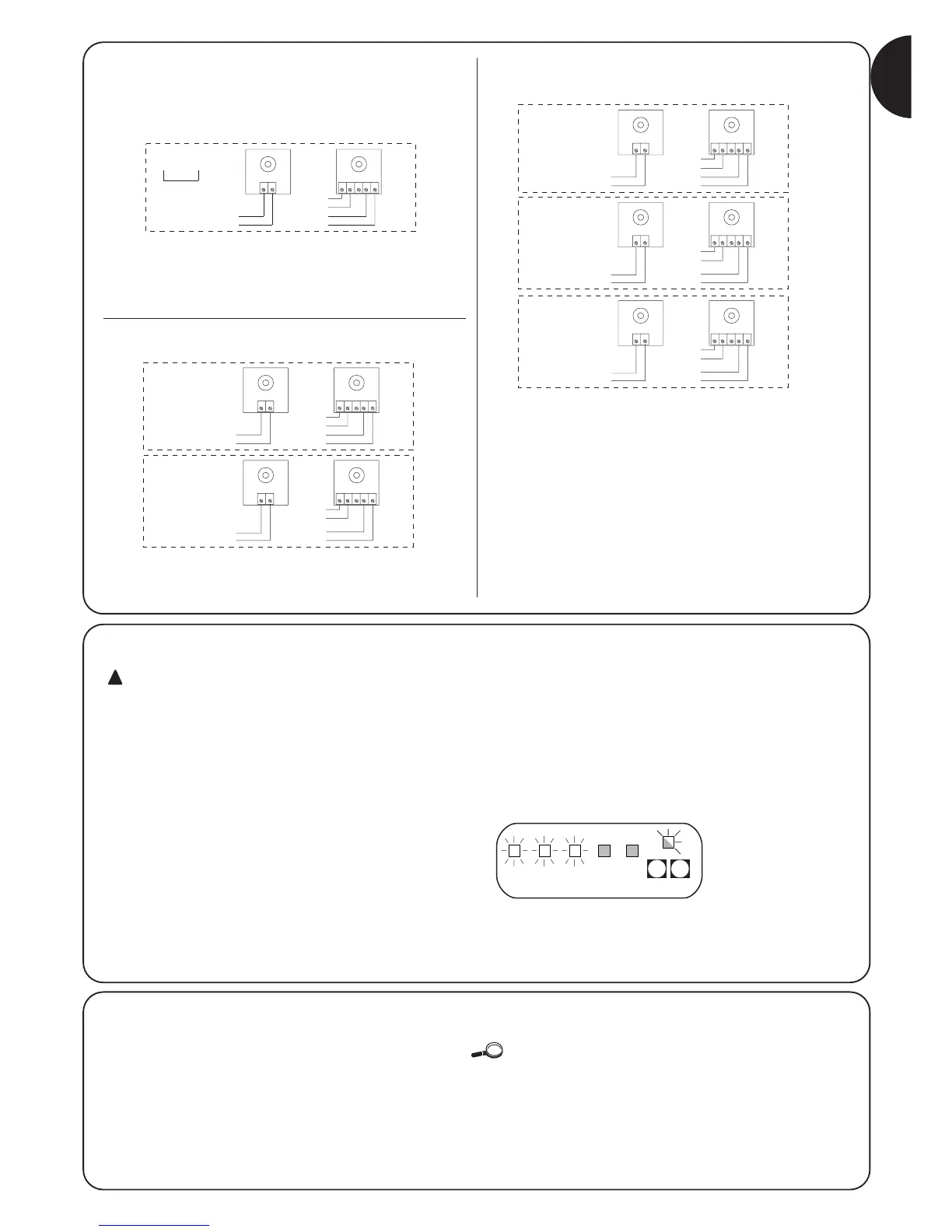
Examples of single-wire photocell connections
Connecting the PHOTO photocell only.
(ref. fig. 2)
N.B.: The PHOTO1 (21) input is not used and must therefore be
connected to terminal 13 in order to allow the PHOTOTEST function
to work exclusively with PHOTO.
PHOTO and PHOTO1 connections
N.B.: observe the indicated power input connections and enable the
SYNCHRONISM function (available on all the NICE photocells).
PHOTO, PHOTO1 and PHOTO2 connections
(ref. fig. 3)
N.B.: observe the indicated power input connections and enable the
SYNCHRONISM function (available on all the NICE photocells).
12345
12
TX
PHOTO
RX
13
14
13
15
16
17
20
21
12345
12
12345
12
PHOTO
PHOTO
1
TX RX
TX RX
13
14
14
13
15
16
17
20
16
15
17
21
12345
12
12345
12
12345
12
PHOTO
TX RX
PHOTO 1
TX RX
PHOTO 2
TX RX
13
14
14
13
14
13
15
16
17
20
16
15
17
21
16
15
17
23
2.4.5) Checking connections
The next operations involve work being done on live
circuits, some parts have mains voltage running through
them and are therefore EXTREMELY DANGEROUS! Pay the
greatest of attention to what you are doing and NEVER
WORK ALONE!
After making connections, the whole system must be checked.
• Power the control unit and check that all the Leds flash rapidly for
a few seconds.
• Check that terminals 1-2 are powered and that voltage is about
24Vac on terminals 15-16; if this is not the case, unplug the unit
immediately and carefully check the connections and input
voltage.
• After the initial rapid flashing, the “OK” Led shows the control unit
is working correctly by flashing regularly at 1 second intervals.
When there is a variation in the inputs, the “OK” led flashes rapidly
twice to show that the input has been recognised.
• If the connections are correct, the relative Led on the NC inputs,
i.e. STOP, PHOTO and PHOTO1 must be on. The STEP-BY-STEP
and AUX Leds must be off (if PHOTO2 and AUX are present and
programmed correctly, the AUX Led must be on).
• Make sure that the relative Leds switch on and off when the
devices connected to the inputs are operated.
STOP Photo Photo
1
Step
by
Step
AUX
STOP PP
P1 P2
2.5) Searching for mechanical stops
After these checks have been made the control unit can be made to
automatically search for the mechanical stops; this operation is
required as the A400 control unit must “measure” the duration of the
opening and closing manoeuvres.
If the control unit has never been installed, i.e. there is no valid duration in
its memory, the procedure is activated automatically. If this procedure has
already been carried out, in order to reactivate it, the memory must first be
deleted (see the “Memory programming – deletion” chapter). To find out
whether the memory contains duration data, switch power to the unit off and
on. If all the Leds flash rapidly for 10 seconds, the memory is empty; if they
flash for just 3 seconds, the memory already contains motor work times.
 Loading...