POWER SUPPLY
FLASHING LAMP
AERIAL
COMMON 24 V
24V
0
0
24V (TX PHOTO)
SCA 24Vac
STOP (NC)
PHOTO (NC)
PHOTO 1 (NC)
STEP-BY-STEP (NO)
AUX (NO)
PHOTOTEST
24Vac
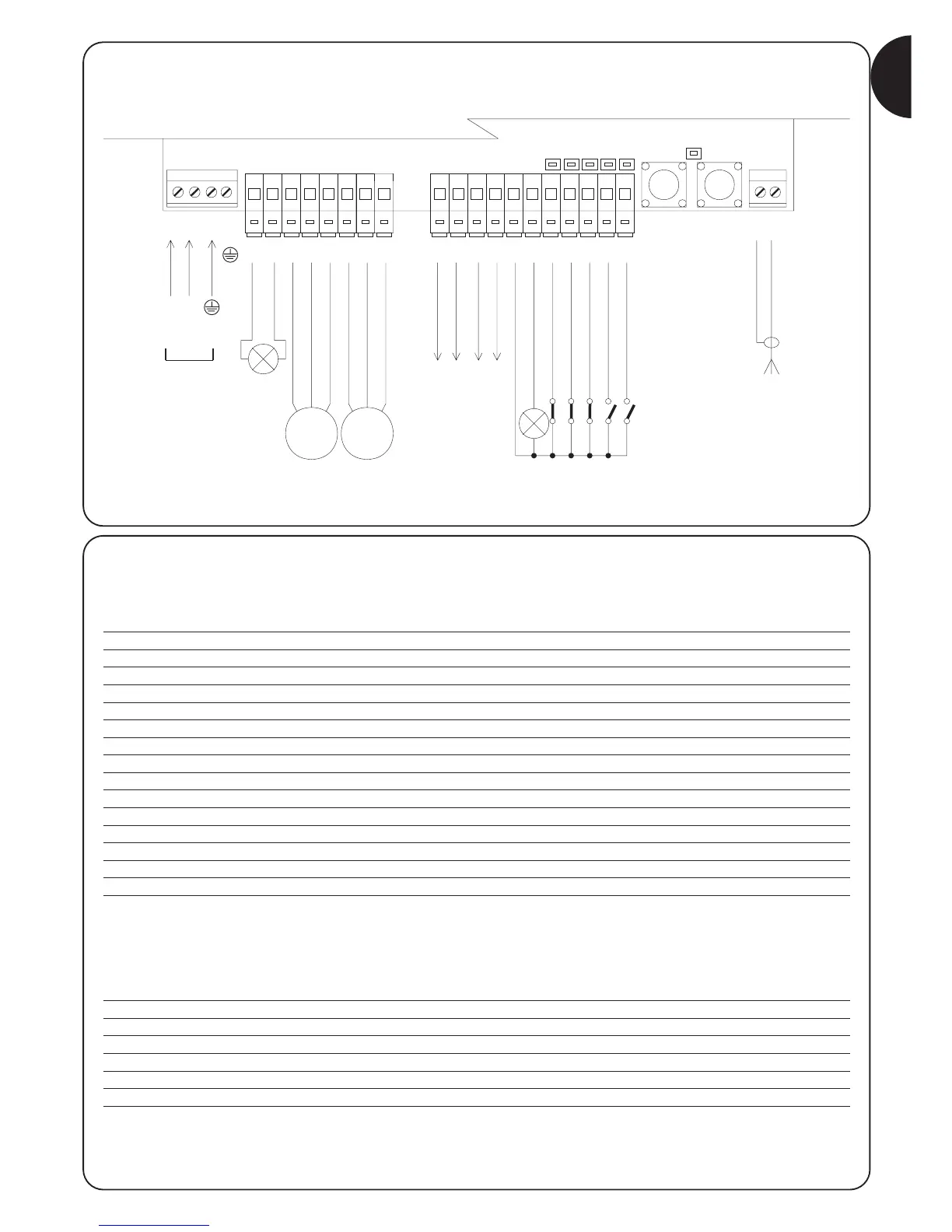
2.4.2) Description of connections
A brief description of the possible control unit output connections follows
Terminals Functions Description
1÷3 Power input Mains power supply
4 Earth Motor earth connection
56 Flashing lamp Connection of flashing lamp to mains voltage (max. 40W)
7÷9 Motor 1 * M1 motor connection (lower leaf)
10÷12 Motor 2 * M2 motor connection (upper leaf)
13÷14 Phototest TX photocell power output (24Vac max. 100mA)
15÷16 24 Vac Power output for services, RX photocells, etc. (24Vac max. 150mA)
17 Common 24 Vac Common for all inputs/outputs
18 SCA Gate open indicator (24Vac max. 1.5W)
19 Stop Input NC with STOP function (emergency, safety shutdown)
20 Photo Input NC for safety devices (photocells, pneumatic edges)
21 Photo1 Input NC for safety devices (photocells, pneumatic edges)
22 Step-by-Step Input for cyclical functioning (OPEN STOP CLOSE STOP)
23 AUX ** Auxiliary input
24÷25 Aerial Input for the radio receiver aerial
* With 2 motors, the first to move in the opening cycle is the M2 motor.
The A400 control unit automatically recognises if there is just one motor installed which must be connected to M2.
** The auxiliary input AUX may be programmed in one of these functions (see chapter 4 “Programming”):
Function Input type Description
PARTIAL OPEN type 1 NO Completely opens the leaf connected to the M2 motor
PARTIAL OPEN type 2 NO Opens the 2 leafs halfway
OPEN NO Only carries out the open manoeuvre
CLOSE NO Only carries out the close manoeuvre
PHOTO 2 NC PHOTO 2 function
DISABLED -- No function
Unless otherwise programmed, the AUX input performs the PARTIAL OPEN type 1 function
OPEN
COMMON
CLOSE
OPEN
COMMON
CLOSE
WARNING: Connection of photocells with Phototest (see chapter 2.4.4)
Note: pre-programmed control unit set for automatic measuring of working time (see chapter 2.5.1)
 Loading...