3
GB
The A400 control unit operates on the basis of a system (current
sensitivity) which checks the load of the motors that are connected
to it. This system automatically detects the travel stops and
recognises obstacles during normal movement (anti-crush safety
feature).
This feature makes installation very simple given that no adjustments
need to be made.
The control unit is pre-programmed for normal functions while more
specific functions can be chosen following a simple procedure.
The level of current also depends on other factors apart from load, e.g.:
voltage variations, the type of motor, the value of the starting capacitor, etc…
The A400 control unit has been optimised for the motors used in the Wingo
actuators, other types of motor may cause the A400 control unit to work
incorrectly.
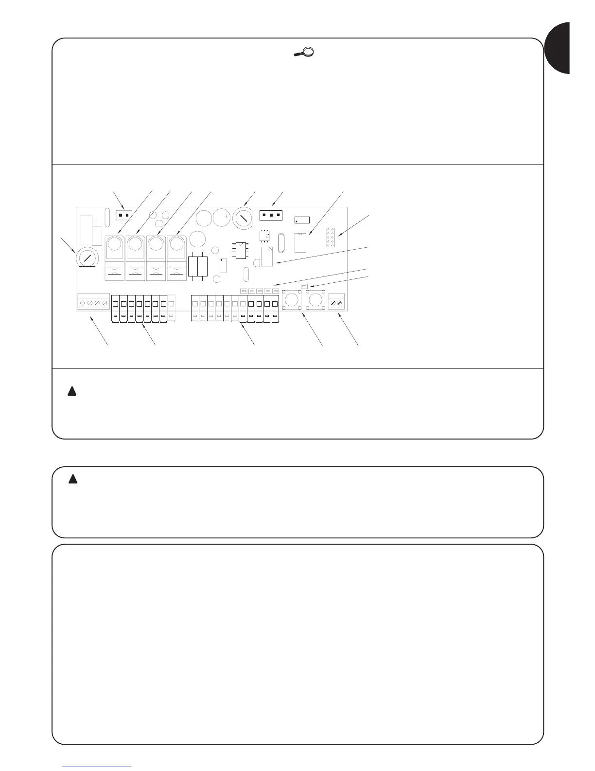
A Primary transformer connector
B Common relay
C Open/Close relay
D M1 motor relay
E M2 motor relay
F Very low voltage fuse (500mA)
G Secondary transformer connector
H Microprocessor
I Radio receiver connector
L Phototest relay
M “INPUTS” Led
N “OK” Led
O Terminal for radio aerial
P Programming buttons
Q Input-output terminals
R Terminals for motors and flashing light
S Power input terminals
T Line fuse (5A)
In order to protect the operator and the electronic
card from accidental damage, only the control unit
terminal boards and programming buttons are normally
accessible.
Only remove the cover if necessary and always disconnect
the mains power supply beforehand.
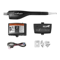
1) Product description:
Automatic gate and door systems may only be
installed by qualified fitters in the full respect of the law.
Comply with the warnings shown in the “Warnings for
fitters” file.
2.1) Preliminary checks
Before starting installation make sure that all the material is suitable
for installation and complies with legal requirements. As well as
checking all the points shown in the “Warnings for fitters” file, this
section also contains a specific check list for the A400 control unit.
• The “mechanical stops” must be able to stop the gate from moving
and must absorb all the kinetic energy accumulated during
movement without difficulty.
• Power the control unit using a 3 x 1.5 mm2 cable.
Should the distance between the control unit and the earth
connection exceed 30 m, install an earth plate near the control
unit.
• Use wires with a minimum cross section of 0.25 mm2 to connect
low voltage safety circuits.
Use shielded wire if the length exceeds 30 m and connect the
earth braid only on the control unit side.
• Do not connect cables in buried boxes even if they are completely
watertight.
• If correctly installed, the control unit is protected to IP55 and can
therefore be installed outdoors.
Fix the control unit on a permanent surface that is perfectly flat and
adequately protected against knocks, making sure that the
bottom remains at least 40 cm from the ground.
• Only fit cable holders or pipe leads in the lower part of the
container (see figure 1, figure 1a).
2) Installation:
 Loading...