EN-7
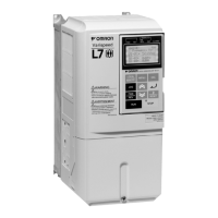
Leakage current is caused by the Inverter. Therefore, if the distance between the ground electrode and the
ground terminal is too long, potential on the ground terminal of the Inverter will become unstable.
• When more than one Inverter is used, do not to loop the ground wire.
Fig 1 Ground Wiring
Control Circuit Wiring Precautions
Consider the following precautions for wiring the control circuits.
• Separate control circuit wiring from main circuit wiring (terminals R/L1, S/L2, T/L3, B1, B2, U/T1, V/T2,
W/T3, , 1, 2, and 3, PO, NO) and other high-power lines.
• Separate wiring for control circuit terminals MA, MB, MC, M1, M2, M3, M4, M5, and M6 (contact out-
puts) from wiring to other control circuit terminals.
• If an optional external power supply is used, it should be a UL Listed Class 2 power supply.
• Use twisted-pair or shielded twisted-pair cables for control circuits to prevent operating faults.
• Ground the cable shields with the maximum contact area of the shield and ground.
• Cable shields have to be grounded on both cable ends.
Main Circuit Terminals
Main circuit terminal functions are summarized according to terminal symbols in Table 1. Wire the terminals
correctly for the desired purposes.
Table 1 Main Circuit Terminal Functions (200 V Class and 400 V Class)
Control Circuit Terminals
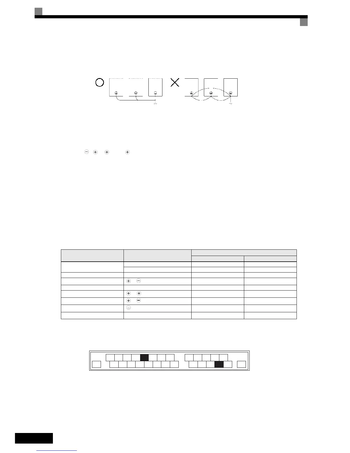
Fig 2 shows the control terminal arrangement. The functions of the control circuit terminals are shown in
Table 2. Use the appropriate terminals for the correct purposes.
Fig 2 Control terminal arrangement
Purpose Terminal Symbol
Model: CIMR-L7Z
200 V Class 400 V Class
Main circuit power input
R/L1, S/L2, T/L3 23P7 to 2055 43P7 to 4055
R1/L11, S1/L21, T1/L31 2022 to 2055 4022 to 4055
Inverter outputs U/T1, V/T2, W/T3 23P7 to 2055 43P7 to 4055
DC bus terminals
1,
23P7 to 2055 43P7 to 4055
Braking Resistor Unit connection B1, B2 23P7 to 2018 43P7 to 4018
DC reactor connection
1, 2
23P7 to 2018 43P7 to 4018
Braking Unit connection
3,
2022 to 2055 4022 to 4055
Ground 23P7 to 2055 43P7 to 4055
Control Power Supply PO, NO 23P7 to 2055 43P7 to 4055
OK
NO
+V
SC SC SC
BB
A1 AC
E(G)
S1
S2
S3 S4
S5 S6 S7 BB1
M5
M6
M3
M4
MA MB MC
M1
M2
E(G)
 Loading...