5 Setup and Wiring
5 - 12
Vision System FH/FZ5 series Hardware Setup Manual (Z366)
Connect to the terminal block by using the terminal connector, male: FH-XCN-L, which is packaged with
Sensor Controller.
Use the wire of a suitable size (AWG 12 to 16) according to the current consumption. Keep the power
supply wires as short as possible: Max. 2m.
1 Insert the end of the signal line, electric wire, into the terminal block connector (male).
Tighten the three screws on the connector top to secure the wire.
Recommended tightening torque: 0.5 - 0.6 N
•m
2 Insert the terminal block connector (male) into the terminal block connector (female) on the FH
Sensor Controller side.
3 Secure the terminal block connector (male) by tightening the screws on the right and left sides
of it with a flathead screwdriver. Recommended tightening torque: 0.5 - 0.6 N
•m
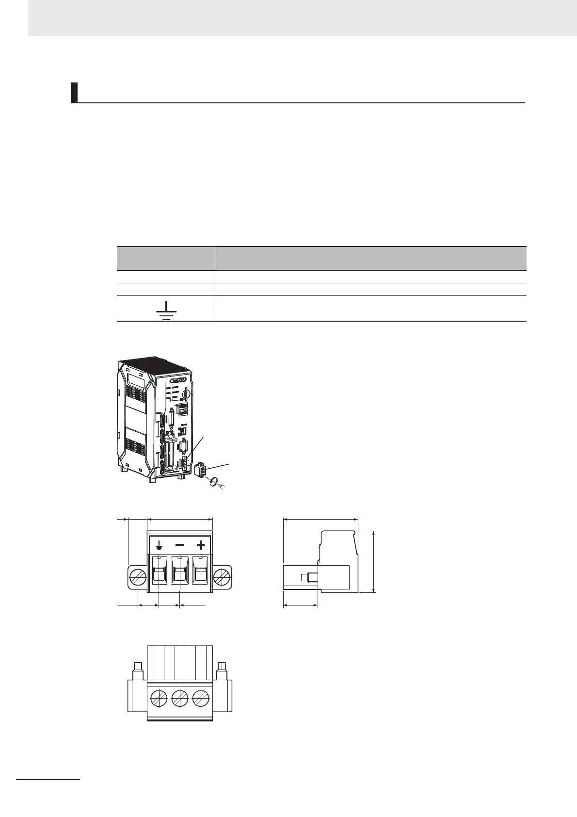
Connection of Terminal Block of FH-L Series
Power Terminal Con-
nector
Function
+ Connect to the DC output terminal +V of 24 VDC.
- Connect to the DC output terminal -V of 24 VDC.
Connect to the earth.
Terminal block connector (female)
Terminal block connector (male)
18.215.854.7
8.3
15
5.08 5.08
(Unit: mm)

 Loading...


