6-3
6
6-3. Normal Display Operations and Functions
Normal display functions
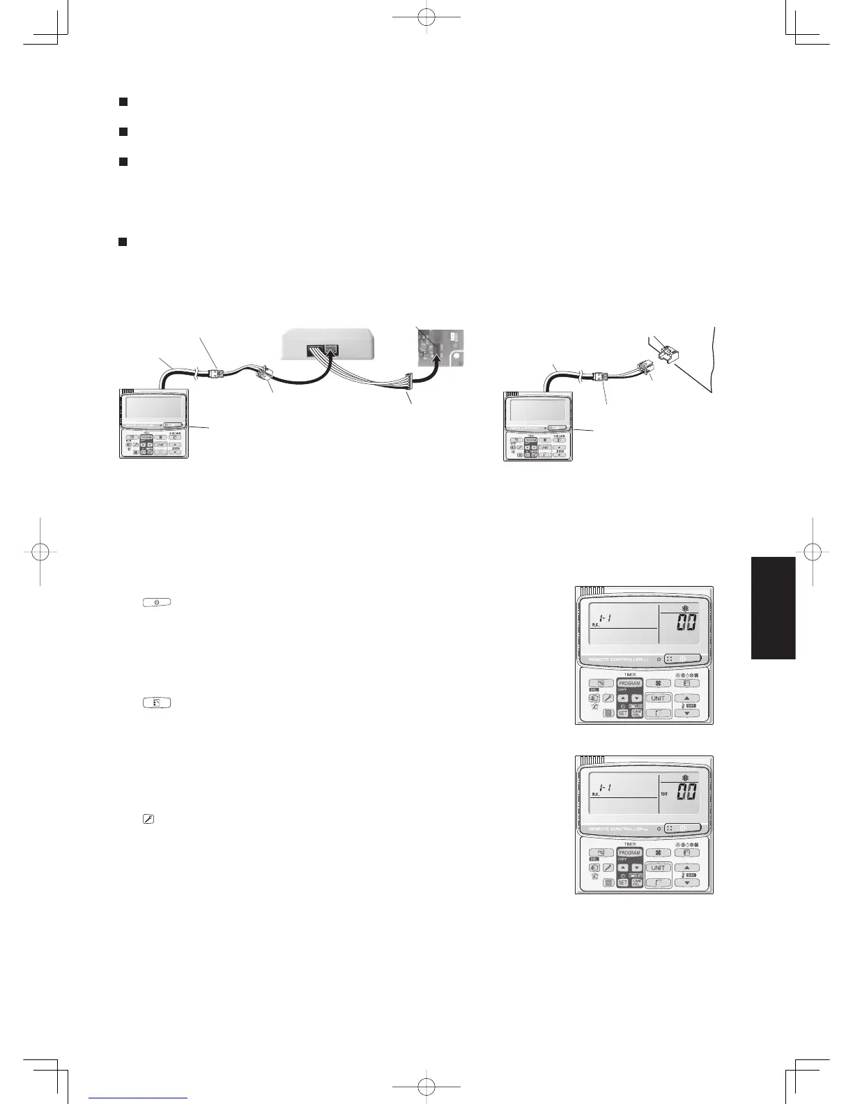
• Connect the special service checker wiring to the outdoor unit PCB.
The connection is shown in the fi gure below.
Special service
checker wiring
Relay connector (2P, white)
PCB connector (3P, blue)
Remote controller Assy
Interface for outdoor unit maintenance
remote controller (No. CV6233039848)
Outdoor unit
control PCB
RC (5P, red)
PCB connector
(5P, red)
Fig. 6-1
Fig. 6-2
Temperature monitor
• Displays the indoor/outdoor unit sensor temperatures.
Outdoor unit alarm history monitor
• Displays the outdoor unit alarm history.
Setting modes
• Setting mode 1 and setting mode 2 are used to make the outdoor EEPROM setting.
* It is not necessary to disconnect the communications line in the inter-unit control wiring if it has already been con-
nected at this time.
* Setting modes 1 and 2 can be used even when the outdoor unit is independent (when 1 maintenance remote con-
troller is connected to 1 outdoor unit and automatic address setting for the indoor units has not been completed).
* Displays the overall system status for that refrigerant system.
z
All units start/stop (Fig. 6-1)
<Operation>
The button can be used to start and stop all the indoor units.
• The LED turns ON when 1 or more indoor units is operating.
• The LED blinks when an alarm has occurred at 1 or more indoor units
during operation.
z
Switching between cooling/heating (Fig. 6-1)
<Operation>
The button switches between heating and cooling modes.
• The specifi cations are equivalent to the heating/cooling input that was
present on earlier outdoor unit PCBs.
• The display shows the operating mode of the indoor unit with the lowest
number.
z
All units test run (Fig. 6-2)
<Operation>
The button switches test run ON/OFF for all indoor units.
• Press and hold for 4 seconds to turn ON.
“Test run” is displayed while the test run is in progress.
• Conditions of test runs that are started from the unit remote controller
are not displayed on the outdoor unit maintenance remote controller.
For 3-phase models
Special service checker wiring
RC (3P, blue)
Outdoor
unit PCB
PCB connector
(3P, blue)
Relay connector (2P, white)
Remote controller Assy
Sec6.indd3Sec6.indd3 2012/02/2811:49:482012/02/2811:49:48
 Loading...