1
1-47
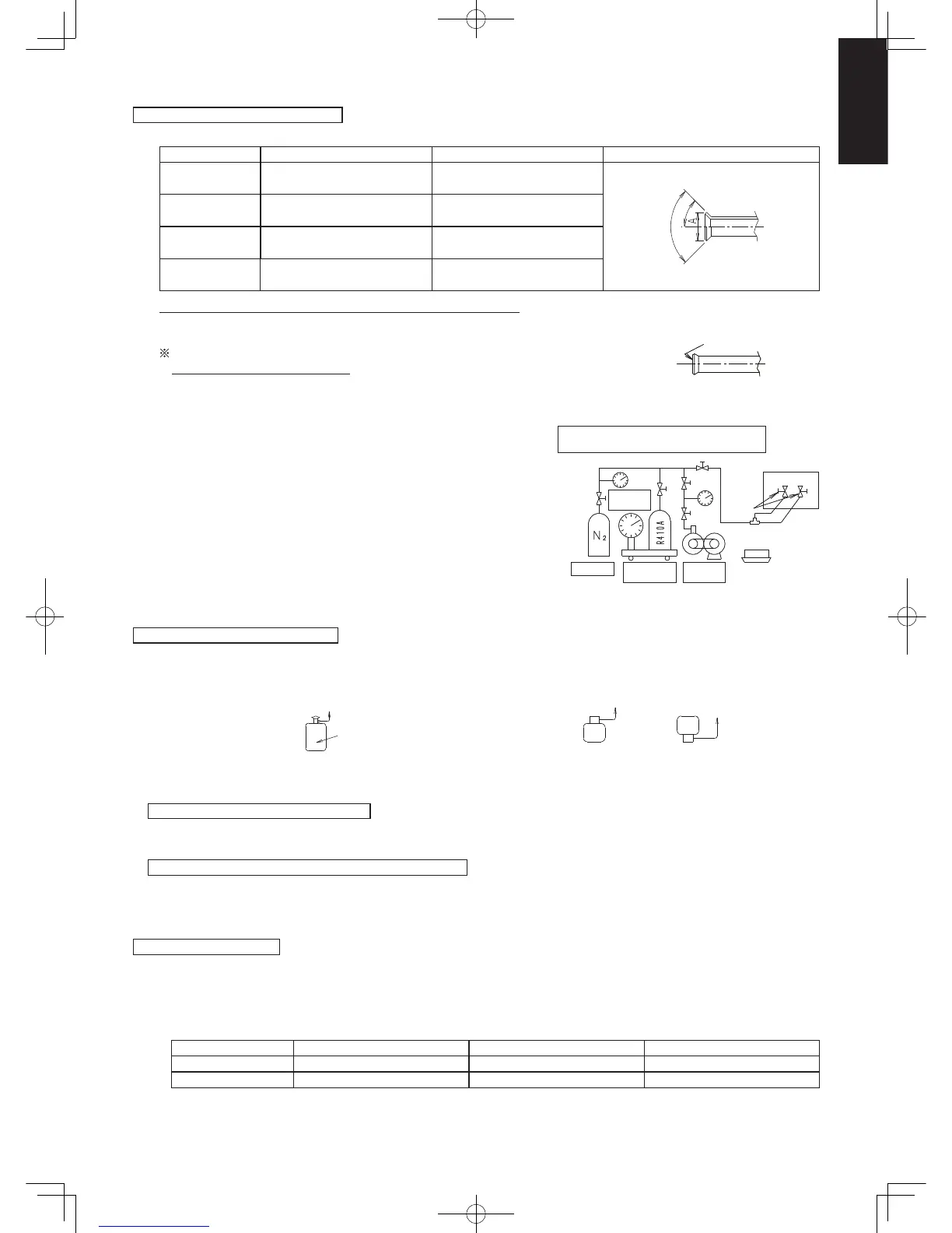
Precautions for flare nut installation
●
Dimensions when adding flare nuts and the tightening torque
Piping size Tightening torque Flare section dimensions A Flare confi guration
ø6.35
14.2N
•
m ~ 17.2N
•
m
(1.4kgf
•
m ~ 1.7kgf
•
m)
8.7 ~ 9.1
90° ± 2°
45
° ±1
°
ø9.52
32.7N
•
m ~ 39.9N
•
m
(3.3kgf
•
m ~ 4.0kgf
•
m)
12.8 ~ 13.2
ø12.7
49.5N
•
m ~ 60.3N
•
m
(5.0kgf
•
m ~ 6.0kgf
•
m)
16.2 ~ 16.6
ø15.88
68.0N
•
m ~ 75.5N
•
m
(6.8kgf
•
m ~ 7.6kgf
•
m)
19.3 ~ 19.7
After piping connection has completed, ensure there is no gas leakage.
●
When tightening the flare nut, coat the flares (inner surface only) with refrigerant oil on the flares.
Firstly, screw in 3-4 turns by hand.
Ensure not to get oil on the screw part.
Refrigerant oil used is ether-based.
●
Once the piping connections are completed, perform leakage inspection using nitrogen gas.
VACUUM PURGING
●
Once the piping connections are completed, perform leakage inspection
using nitrogen gas (leak tightness test) using the 3-way valve for the
outdoor unit and then close it.
(Test the pressure with 3.8 MPa)
●
Ensure to use a vacuum pump (with a back-flow prevention device) for
inside the refrigerant system.
●
Vacuuming process will take place after the leak test.
REGARDING REFRIGERANT FILLING
Precautions during refrigerant filling
●
Ensure to fill only with liquid refrigerant when refilling.
If gas refrigerant is filled, the refrigerant composition will not be
balanced and will cause abnormal operation.
●
If using cylinders as shown in the bottom left diagram; without
a siphon tube inside, turn it upside down and use it.
(It is recommended to use the manifold with the side glass.)
Cylinder with
a siphon tube
Liquid refrigerant
Siphon tube
Cylinder
Cylinder
Gas refrigerant
Possible
Not possible
Liquid refrigerant
●
Use tools that are designed specifically for R410A, for pressure resistance and to prevent mixing impurities.
●
Fill the refrigerant from the 3-way valve’s service port on the liquid-side.
For filling and replacing all refrigerant (For refilling due to a leak)
●
For refilling refrigerant, first collect all residual refrigerant and after vacuum dehydration using the vacuum pump. Refill the
refrigerant according to the prescribed amount stated on the placard affixed to this unit.
Precautions after the pipes’ connection have completed
●
Ensure to open the 3-way valve after completing the piping installation, leak test and vacuuming. If it is closed during operation, it
can lead to compressor failure.
Charging with refrigerant
●
At the time of shipment from the factory, this unit is charged with enough refrigerant for an equivalent pipe length of 30 m. If the
equivalent pipe length used will be 30 m or less, no additional charging will be necessary.
●
If the equivalent pipe length will be between 30 and 50 m, charge with additional refrigerant according to the equivalent length
given in the table below.
●
For standard type
Additional charging amount Equivalent length Minimum length
U-60/71P 50 g/m 50 m 5 m
U-100/125/140P 50 g/m 75 m 5 m
Application for ether-based oilApplication for ether-based oil
Outdoor unit
3-way
valve
Indoor unit
Use nitrogen gas for the leak tightness test.
Using fl ammable gas can cause an explosion.
Pressure
meter
Nitrogen Refrigerant
meter
Vacuum
pump
Outdoor unit
3-way
valve
Indoor unit
Use nitrogen gas for the leak tightness test.
Using fl ammable gas can cause an explosion.
Pressure
meter
Nitrogen Refrigerant
meter
Vacuum
pump
Sec1.indb47Sec1.indb47 2012/03/0717:30:022012/03/0717:30:02
 Loading...