1
1-48
●
Pump down operation
●
Operate the pump down according to the following procedures.
Procedure Notes
1. Confi rm the valve on the liquid side and the gas
side is surely open.
2. Press the PUMP DOWN switch on outdoor
printed board for 1 second or more.
Perform the cooling operation for fi ve minutes or more.
3. Shut the valve on the liquid side surely.
When the valve is shut halfway, the compressor is
occasionally damaged.
ELECTRICAL WIRING
Warning
The units must be connected to the supply cables for fi xed wiring by qualifi ed technician.
Feed the power source to the unit via a distribution switch board designed for this purpose, the switch should
disconnected all poles with a contact separation of at least 3 mm.
When the supply cable is damaged, it must be replaced by qualifi ed technician.
Be sure to install a current leakage breaker, main switch and fuse to the main power supply, otherwise electric
shocks may result.
Be sure to connect the unit to secure earth connection.
If the earthing work is not carried out properly, electric shocks may result.
Wiring shall be connected securely by using specifi ed cables and fi x them securely so that external force of
the cables may not transfer to the terminal connection section.
Imperfect connection and fi xing leads to fi re, etc.
● Ensure to connect the electrical cable connections and clamp the wires securely to the terminal connections using cord clamps so
that no undue force is placed on the wires (power source cable, indoor/outdoor connection cables, earth lead wire).
● Do not install a phase advance capacitor for power factor improvement. (It does not improve the power factor and will cause
abnormal overheating.)
● Do not bind the excess cables together and place them inside this unit.
● Protect the electrical cable with the protective bushing provided so that the cables do no get damaged on the knock hole or etched
portions. If there is space between the electrical cables and the protective bushing occurs, seal it accordingly.
● Tie the cables with the provided binding strap so that they do not touch the compressor and the pipes.
● When setting up the cables, inside of unit install properly so that the front panel will not lift up. Make sure that front panel mount
correctly.
● Use a round type terminal with an insulation sleeve for connecting to the terminal block.
● Use the appropriate screwdriver for tightening the terminal screws. Small sized
screwdriver damages the head of the screw and cannot tighten it properly.
● There is risk of damaging the screw if the terminal screw is over tightened.
Tighten with the appropriate torque.
Screw diameter name Tightening torque N
•
cm (kgf
•
cm)
M4 157 ~ 196 (16 ~ 20)
M5 196 ~ 245 (20 ~ 25)
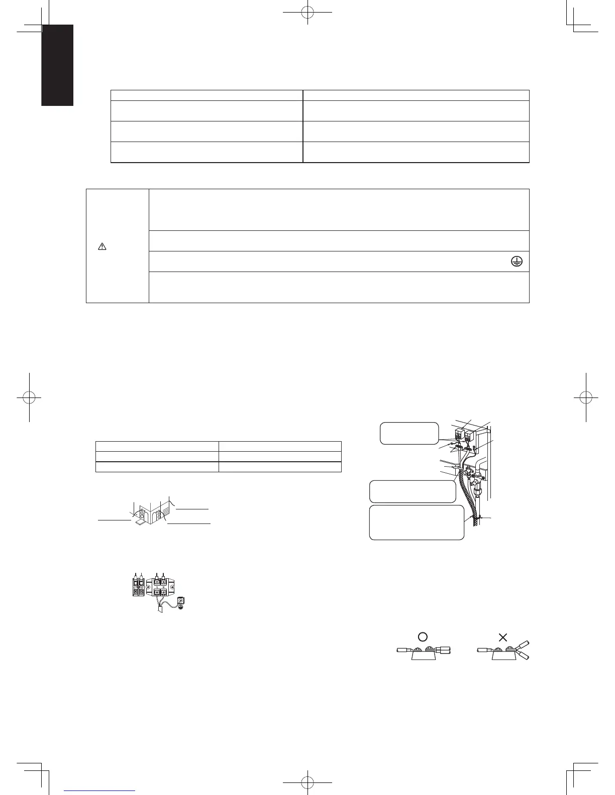
● Direction to pull out wires
Back direction
Sideways direction
Front direction
Seal wiring holes after wiring using included protection bush.
(other holes are for connecting conduit pipe)
● Earth lead wire set up
The earth lead wire shall be longer than other lead wires as shown in the figure for electrical safety in
case it slips out of the cord from the anchorage.
● Be sure to connect the wires correctly to terminal board with connecting the crimp
type ring terminal to the wires.
● If connecting two separate wires to a single crimped terminal, place the two crimped
terminal wires together as shown in Fig. A. (If the arrangement shown in Fig. B is
used, poor contacts or contact damage may result.)
SG
Insulate the
terminal section with
insulation sleeves.
Cord clamp
Cord clamp
Control
terminal block
Power supply
terminal block
Earth lead wire
Tying band
(Standard
accessories)
Firmly secure the power supply
cable, the internal/external
connections and earth wire.
Tie the insulation pipes so that the
power supply cable, control wires,
and earth lead wire do not come into
contact with the compressor and/or
the exposed pipes.
Fig. A (OK) Fig. B (not OK)Fig. A (OK) Fig. B (not OK)
Sec1.indb48Sec1.indb48 2012/03/0717:30:022012/03/0717:30:02
 Loading...