8
Metal Panel
Installing the Operation Panel
(1)
(2)
(3)
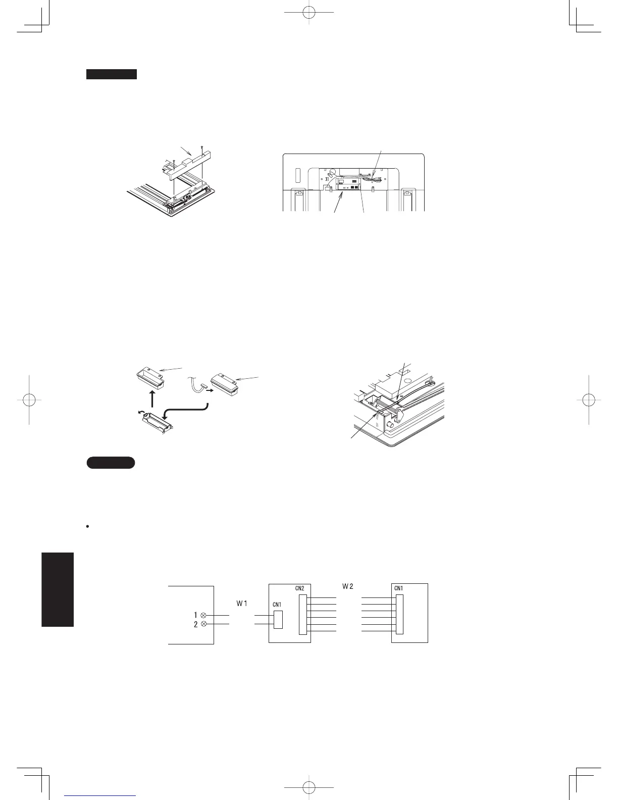
Remove the 2 screws and remove cover A from the back of the panel. (Fig. 8-19)
Fasten the operation panel to the location in the diagram below with the 2 enclosed screws (4
X 10). (Fig. 8-20)
Pass the wiring for the display (W2, 6P white connector) through the back of the panel.
Installing the Display
(1) Cover B is fit into Cover A, so spread the points as indicated in figure 8-21 and remove it.
The tape holding cover B is only to protect it during transport, so remove it and throw it away.
(2) Connect the wiring (W2) for the display that is sticking out from the operation panel and fit the display into the panel.
Make sure the 6P white connector is firmly connected all the way in.
(3) Pass the lead wire for the display through the cutout in the panel, and using the hole in the metal panel, fasten it with the
plastic clamp. (Fig. 8-22)
(4) Attach cover A.
(5)
(6)
Properly route the lead wire of the operation panel and fasten it with the twist lock. (Fig. 8-20)
Install the ceiling panel.
Wiring Diagram
Connections
(1)
(2)
Connect W1 to the remote control terminal strip on the indoor unit. (Polarity does not matter)
Connect the display and the operation panel with W2.
If the wiring to the operation panel is bundled together with other wiring, such as the incoming line from the power source,
it can cause a malfunction, so avoid doing so.
(1)
If something causes the unit’s power source to make noise it will be necessary to resolve the problem, such as by
installing a noise filter.
(2)
For more information about wiring or test runs, refer to Wiring the Receiver and Test Run.
3. Wiring
NOTE
Fig. 8-19
Fig. 8-20
Fig. 8-21
Fig. 8-22
White
Black
Blue
Yellow
Pink
Red
Gray
Cover A
Loop extra wiring and fasten
with a twist lock.
Operation Panel
Enclosed screws (4 X 10)
Cover B
Connect
Spread
Display
Fasten to hole in metal panel
Pass through cutout
Display
Operation Panel
Indoor Unit
Terminal Strip
for Wiring
Remote
Controls
8-22
Sec8.indd22Sec8.indd22 2012/02/2816:14:022012/02/2816:14:02
 Loading...