1
1-38
■
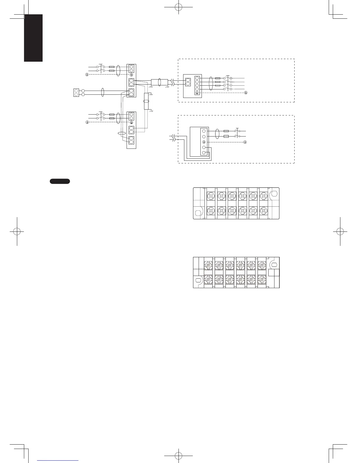
Wiring System Diagrams
NOTE
(1) Refer to “Recommended Wire Length and Wire Diameter
for Power Supply System” for the explanation of “A”, “B”,
“C”, “D” and “E” in the above diagram.
(2) The basic connection diagram of the indoor unit shows the
terminal boards, so the terminal boards in your equipment
may differ from the diagram.
(3) Refrigerant Circuit (R.C.) address should be set before
turning the power on.
(4) Regarding R.C. address setting, refer to the installation
instructions supplied with the remote controller (optional).
Auto address setting can be executed by remote controller
automatically. Refer to the installation instructions supplied
with the remote controller (optional).
L2
L1
U2
U1
L3
N
A
L1
L2
L3
N
U2
R2
U1
R1
R2
R1
L
N
U2
U1
2
1
D
C
B
L
N
L
N
2
1
B
E
C
L
N
A
L
N
2
1
N
L
Power supply
230 – 240V ~50 Hz
Remote
controller
WHT
BLK
Power supply
230 – 240V ~50 Hz
Power supply
230 − 240 V ~50/60 Hz
Ground
Ground
Ground
Ground
* 3-phase model connections
* Single-phase model connections
Ground
Ground
Power supply
400 − 415 V, 3 N~, 50 Hz
Outdoor unit (3-phase)
INV unit
Outdoor unit (single-phase)
INV unit
Ground
Indoor unit
(No. 1)
Indoor unit
(No. 2)
L
N U1U2R1R2
6P terminal board
Power
supply
Unit
control
line
Remote
control
line
U1 Type
R1
R2
U1
U2
NL
Remote
controller
line
Unit
control
wiring
Power
supply
E1 Type
Sec1.indb38Sec1.indb38 2012/03/0717:30:002012/03/0717:30:00
 Loading...