1-20
1
M
P
EC
P
ø15.88
ø15.88
ø9.52
ø9.52
Compressor
Compressor
Heat
exchanger
Heat
EC
P
Defrost Temp
Expantion
valve
Cooling cycle
Heating cycle
exchanger
Heat exchanger
Temp Thermistor
Temp Thermistor
Outdoor-air
Discharge Temp
Thermistor
Suction Temp
Thermistor
4-way
valve
High pressure
switch
High pressure
switch
Thermistor
Accumulator
Accumulator
Gas line
service valve
Muffl er
Muffl er
4-way valve
Electronic ref.
control valve
Liquid line
service valve
Cooling cycle
Heating cycle
Strainer
Strainer Strainer
Heat
exchanger
Heat
exchanger
Strainer
Distributor
Strainer
Distributor
Distributor
Distributor
Freeze-prevention coil
(Attached to the heat exchanger)
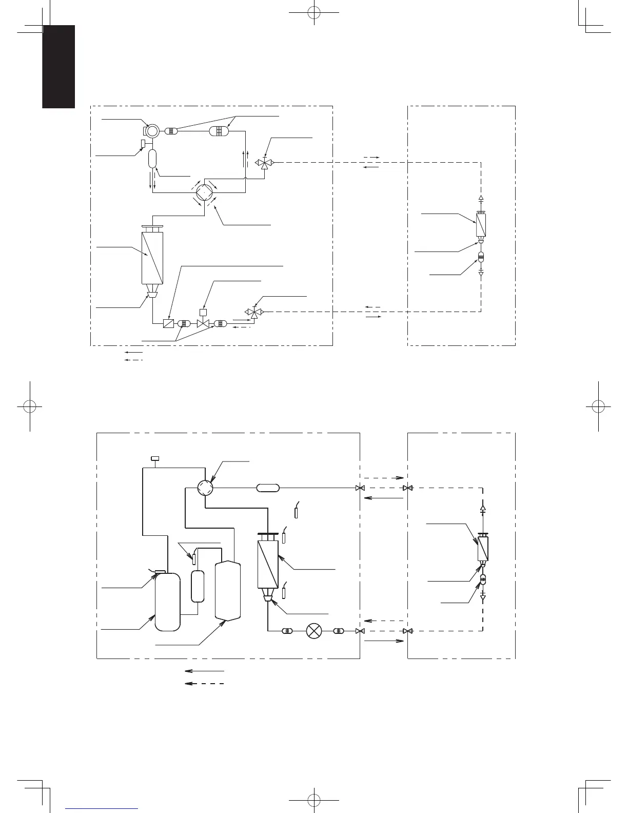
1-3. Refrigerant Flow Diagram
Indoor Unit:
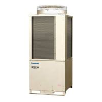
Outdoor Units: U-60PE1R5 / U-71PE1R5
Indoor Unit:
Outdoor Units: U-100PE1R5 / U-125PE1R5 / U-140PE1R5
U-100PE1R8 / U-125PE1R8 / U-140PE1R8
Sec1.indb20Sec1.indb20 2012/03/0717:29:572012/03/0717:29:57
 Loading...