1
1-64
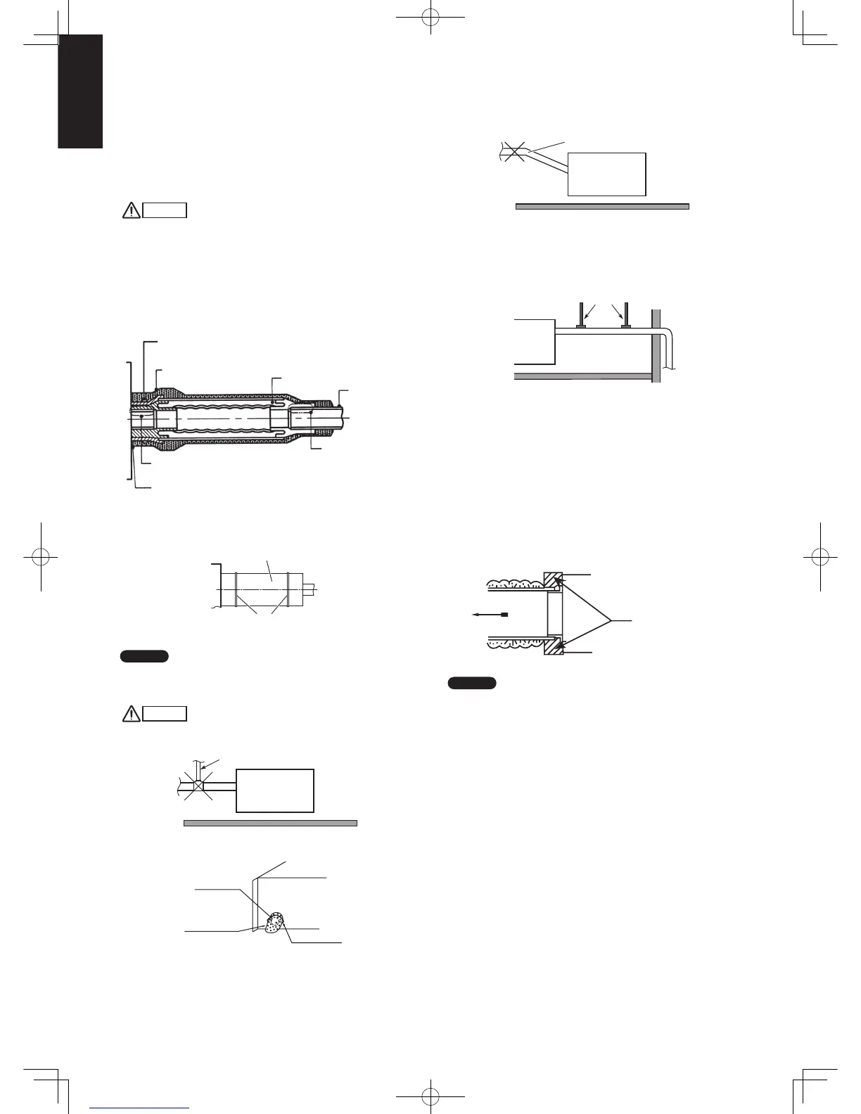
Installing the Drain Pipe
(1) Prepare standard hard PVC pipe (O.D. 32 mm) for the
drain and use the supplied hose band to prevent water
leaks.
The PVC pipe must be purchased separately.
The transparent drain part on the unit allows you to check
drainage. (Fig. 3-8)
CAUTION
●
Do not use adhesive tape at the drain connection port on
the indoor unit.
●
Insert the drain pipe until it contacts the socket, and then
secure it tightly with the hose band.
●
Do not use the supplied drain hose bent at a 90° angle.
(The maximum permissible bend is 45°.)
●
Tighten the hose clamps so their locking nuts face
upward.
Heat insulator (Local
supply) (The thickness
must be at least 8 mm)
Flexible hose with
heat insulator
(Accessory)
PVC pipe
(O.D.ø32)
(Local supply)
Hose clip (Accessory)
It may be required to take off this part for checking
or servicing the drain up motor. Please do not glue.
To be glued
Make sure that there is not clearance here.
(2) After connecting the drain pipe securely, wrap the supplied
packing and drain pipe insulator around the pipe, then
secure it with the vinyl clamps.
Drain insulator (supplied)
Vinyl clamps
(field supply)
NOTE
Make sure the drain pipe has a downward gradient (1/100 or
more) and that there are no water traps.
CAUTION
● Do not install an air bleeder as this may cause water to
spray from the drain pipe outlet.
Prohibited
Air bleeder
Drainage hole
Thermal insulator
(Accessories)
Hose clipr
(Accessories)
● Do not install the pipe with an upward gradient from the
connection port. This will cause the drain water to flow
backward and leak when the unit is not operating.
Upward gradient
Prohibited
● Do not apply force to the piping on the unit side when
connecting the drain pipe. The pipe should not be allowed to
hang unsupported from its connection to the unit. Fasten the
pipe to a wall, frame, or other support as close to the unit as
possible.
Support pieces
Connecting Duct to Indoor Unit
(1) First pull out a filter in the direction of the electrical
equipment box in the unit.
The pre-installed filter will not be used any more.
(2) Then remove the seal packing, bracket and filter attached
to the side of the air intake port.
(3) Install the duct (local supply) for the Dimension of the
installation hole.
Use M5 self-tapp Screws for installation. See the figure at
the botton on page 1-58.
(4) The duct connection of the air outlet needs termal isulation.
Air outlet
Thermal insulator
(Local arrangement)
NOTE
• Select an air-intake grille with a filter at a local shop.
• To get clean air and to extend the service life of the air
conditioner, an air filter must be installed in the air intake.
For installation and cleaning the air filter, consult your dealer
or service center.
Sec1.indb64Sec1.indb64 2012/03/0717:30:112012/03/0717:30:11
 Loading...