Installation
MI3 Rev. G Nov/2015 27
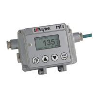
Figure 11: Single Head Configuration with Comm Box
To increase the number of supported sensing heads, you can use a dedicated accessory, see section
10.1.1 Multi-Channel Box, page 64.
5.2.2 Comm Box (DIN)
The multiple sensing head configuration consists of a modular communication box provided in a DIN
rail mountable plastic enclosure for supporting 4 sensing heads simultaneously. The DIN rail
communication box provides an externally accessibly user interface. The terminal strip connectors are
used to simplify the field wiring.
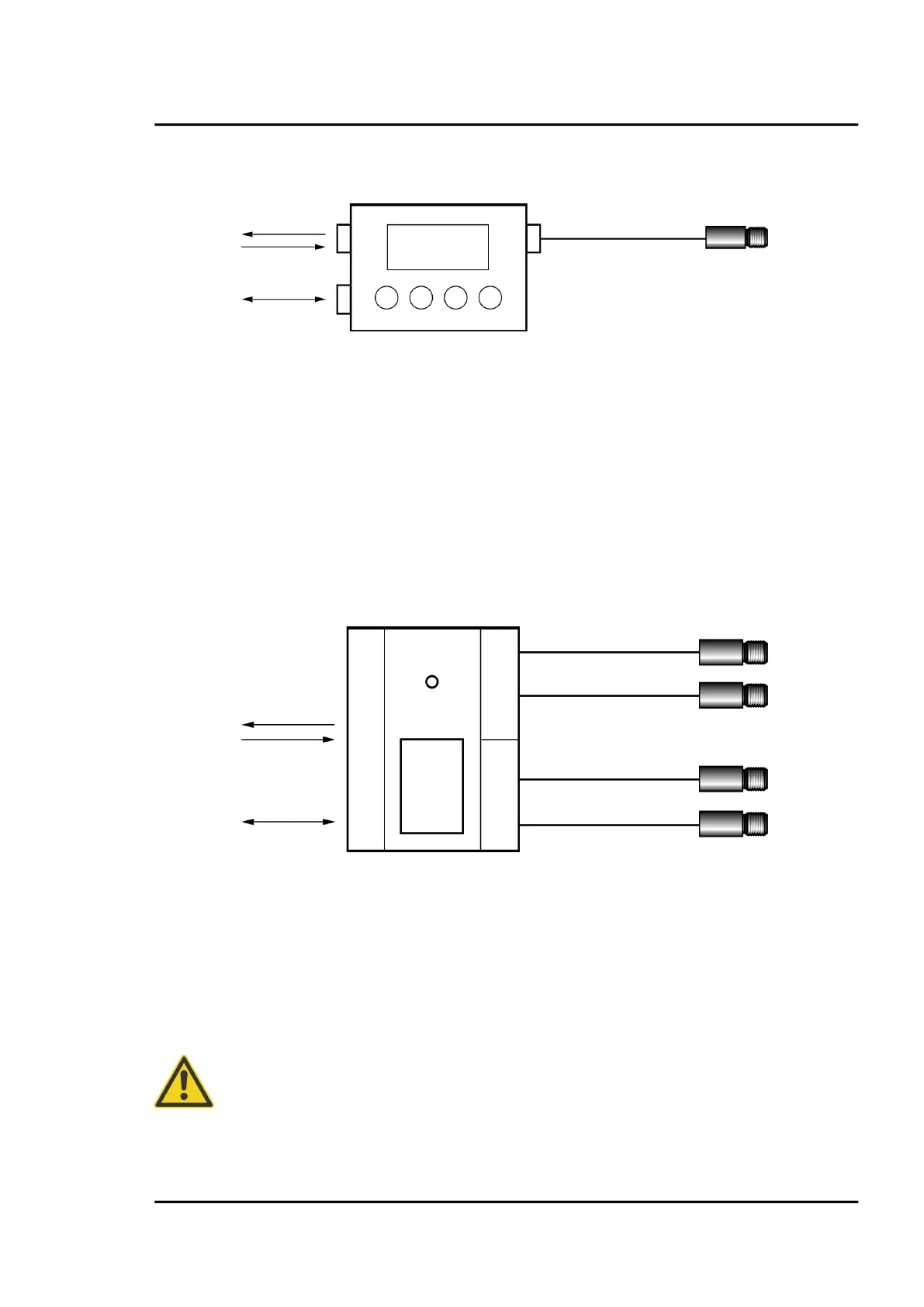
Figure 12: Multiple Head Configuration with DIN Rail Comm Box
5.3 Wiring, Head Cable
The user has to install the sensor cable on the communication box. It may be shortened, if necessary,
but keep a minimal length of 20 cm (7.9 in).
Do not bend the sensing head cable tighter than a radius of 25 mm (1 in.) for the standard heads (PUR
cable) and 15 mm (0.6 in.) for the high ambient temperature heads (Teflon cable) respectively!
To prevent possible fluctuating temperature readings or damages to the device make
sure that the sensor head is grounded before use!
Power supply,
2 analog
outputs,
3 inputs
or
DIN Rail Comm Box
(RAYMI3MCOMM)
Power supply
1 alarm output,
1 trigger
input
Max. 8 Sensing Heads
(RAYMI3…)
Total length:
max. 30 m (98 ft)
Total length:
max. 30 m (98 ft)
 Loading...