Profibus
MI3 Rev. G Nov/2015 89
14 Profibus
Profibus DP-V0 defines a cyclical data exchange between a master (e.g. a PLC) and a slave (MI3
sensor). At start-up first an array of parameters (Profibus specific data) is sent from the master to the
slave, followed by an array with the configuration (sensor specific presetting’s taken from the GSD
file) also sent from the master to the slave.
After start-up the bus switches to the data exchange state. In this state in- and output data gets
exchanged cyclically between master and slave. The input data is sent from the slave to the master
and contains mainly the measured temperatures of the MI3 sensor, see section 14.2.2 Input Data,
page 93. The output data is sent from the master to the slave and contains a set of selected sensor
parameters, see section 14.2.3 Output Data, page 94. In case of an error in start-up phase or during
data exchange diagnostic data is sent to the master, see section 14.2.4 Diagnose Data, page 94.
Each Profibus device comes with a device description file (GSD file) which is read by the
programming software of the master to define the slave.
Specification:
Version: Profibus DP-V0
Physical layer: RS485, 2 wire, electrically isolated
Baud rate: 9.6 kBit/s to 12 MBit/s (automatic negotiated)
Connection terminal or Sub-D or M12
Address range: 1 to 125 (for the Profibus device)
ID 0D36
GSD Datei RAY_0D36.gsd
Head support up to 8 sensing heads (MI3 or MI3100)
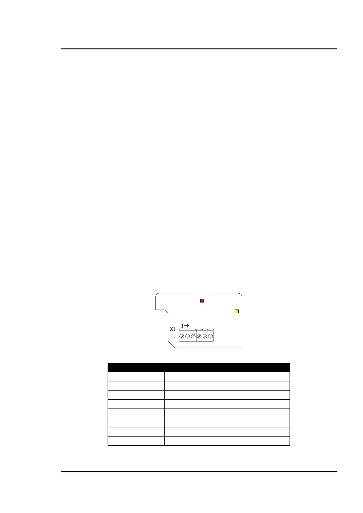
14.1 Wiring
14.1.1 Comm Box (metal)
GND (output, used for external termination)
+ 5 V (output, used for external termination)
blinking, no data communication
Figure 76: Profibus Terminal for Comm Box (metal)
 Loading...