Profibus
94 Rev. G Nov/2015 MI3
14.2.3 Output Data
The device does not have output data in the original meaning. But the output data may be used to
change the initialization of the device (which was set once at start-up) when the bus is in data
exchange mode.
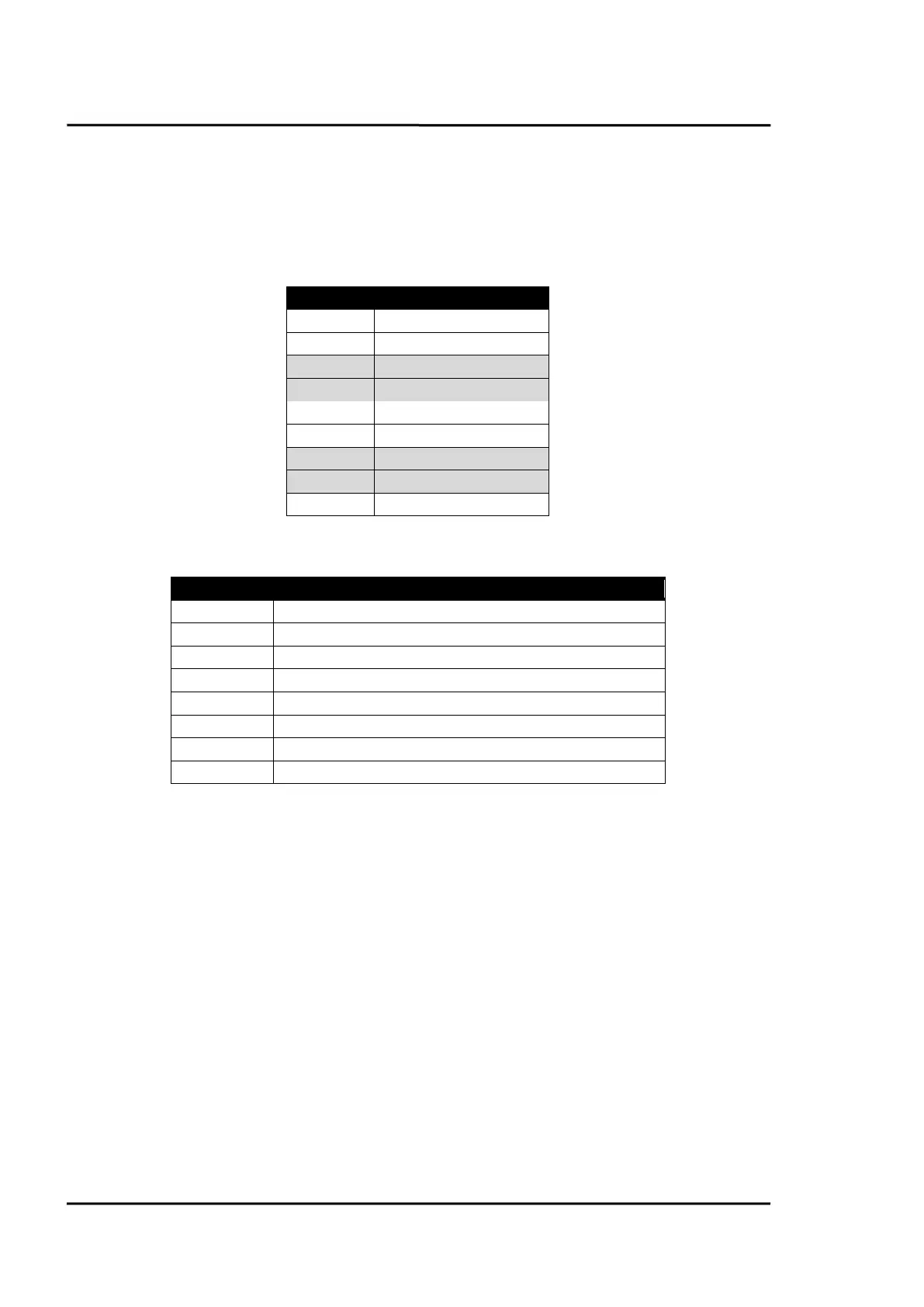
To do so the following structure is defined:
The <Type of parameter> comes with the format described in section 14.2.1 Parameter Data, page 92,
and can be set to the following parameters:
background temperature (background temperature compensation)
If <Type of parameter> is set to 0 then the output data gets ignored. So it should be set to 0 as default.
Attention: You should be aware that always all heads are updated! So you have to set all eight (or as
much as heads are connected) parameters to the correct value!
14.2.4 Diagnose Data
The device uses the first 32 bytes of the Identifier Related Diagnosis.
The first 6 bytes consist of Standard Diagnosis dedicated to bus parameters. In this field byte 4 and 5
give the unit identifier (0D36 in our case).
 Loading...