3
Device structure
Electronics
Operating Instructions – MOVIMOT
®
flexible
23
3.7 Electronics
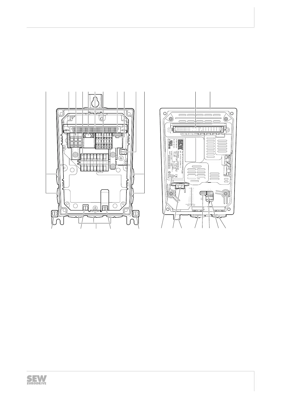
3.7.1 Electronics cover (inside) and connection box
Design MMF1.
The following figure shows the connection box and the bottom side of the electronics
cover:
D C B A1 T2 U V W
S1 1 2 3 4 1 2 3 4 S2
ON
On
Off
f1 f2
ON
3
5
64
7
[9]
[2] [3] [8][4] [6][5] [7] [1][1]
[10]
[10] [10][10][1]
[10] [6] [11]
[19]
[14] [13][15][18] [17] [16] [12]
29487275019
[1] Cable glands
[2] Connection box
[3] Connection line L1, L2, L3
[4] Connection for motor, brake and temperature sensor
[5] Braking resistor connection
[6] Plug connector connection unit for electronics cover
[7] Electronics terminal strip
[8] Engineering interface
[9] MOVILINK
®
DDI connection
[10] Screws for PE connection
[11] Electronics cover
[12] Potentiometer f1 (underneath the screw plug)
[13] Potentiometer t1
[14] DIP switches S1/1 – S1/4
[15] DIP switches S2/1–S2/4
[16] Potentiometer f2 (underneath the screw plug)
[17] Plug connector
[18] Replaceable memory module
[19] Electronics cover nameplate
29129451/EN – 12/2019
 Loading...