5
Electrical installation
Terminal assignment
Operating Instructions – MOVIMOT
®
flexible
58
5.5 Terminal assignment
INFORMATION
The terminals X3 for connecting the braking resistor can be connected to an optional,
internal braking resistor. As an alternative, you an connect an external braking resis-
tor if the power rating of this braking resistor is not sufficient.
Proceed as follows to do so:
• Loosen the connections of the internal braking resistor.
• Insulate and fasten the connections of the internal braking resistor. Make sure all
connections leading to other components are electrically insulated.
• Connect the external braking resistor again. Observe the installation instructions
of the device and of the external braking resistor.
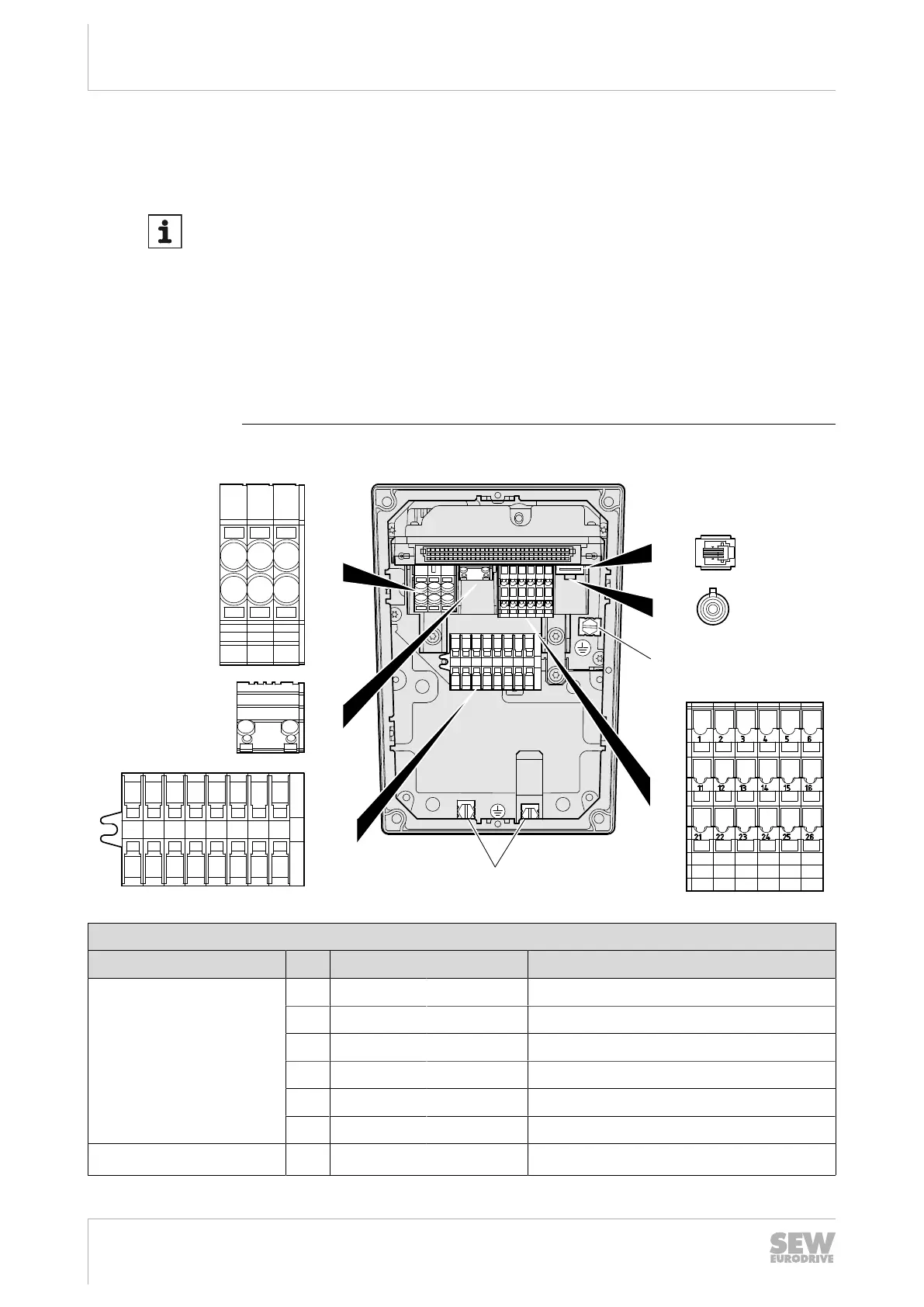
The following figure shows the terminal assignment in the connection box of the
device:
D C B A1 T2 U V W
1 2 3
11 12 13
X1
X31
X9
X3
X2_A
A1 T2 UD C B V W
PE
PE
1 2 3 4
11 12 13 14
21 22 23 24
5 6
15 16
25 26
X16
30531827851
Assignment
Terminal No. Name Marking Function
X1
line terminals
1 L1 Brown Line connection, phase L1 – IN
2 L2 Black Line connection, phase L2 – IN
3 L3 Gray Line connection, phase L3 – IN
11 L1 Brown Line connection, phase L1 – OUT
12 L2 Black Line connection, phase L2 – OUT
13 L3 Gray Line connection, phase L3 – OUT
– PE – PE connection
29129451/EN – 12/2019
 Loading...