5
Electrical installation
Connection diagram
Operating Instructions – MOVIMOT
®
flexible
66
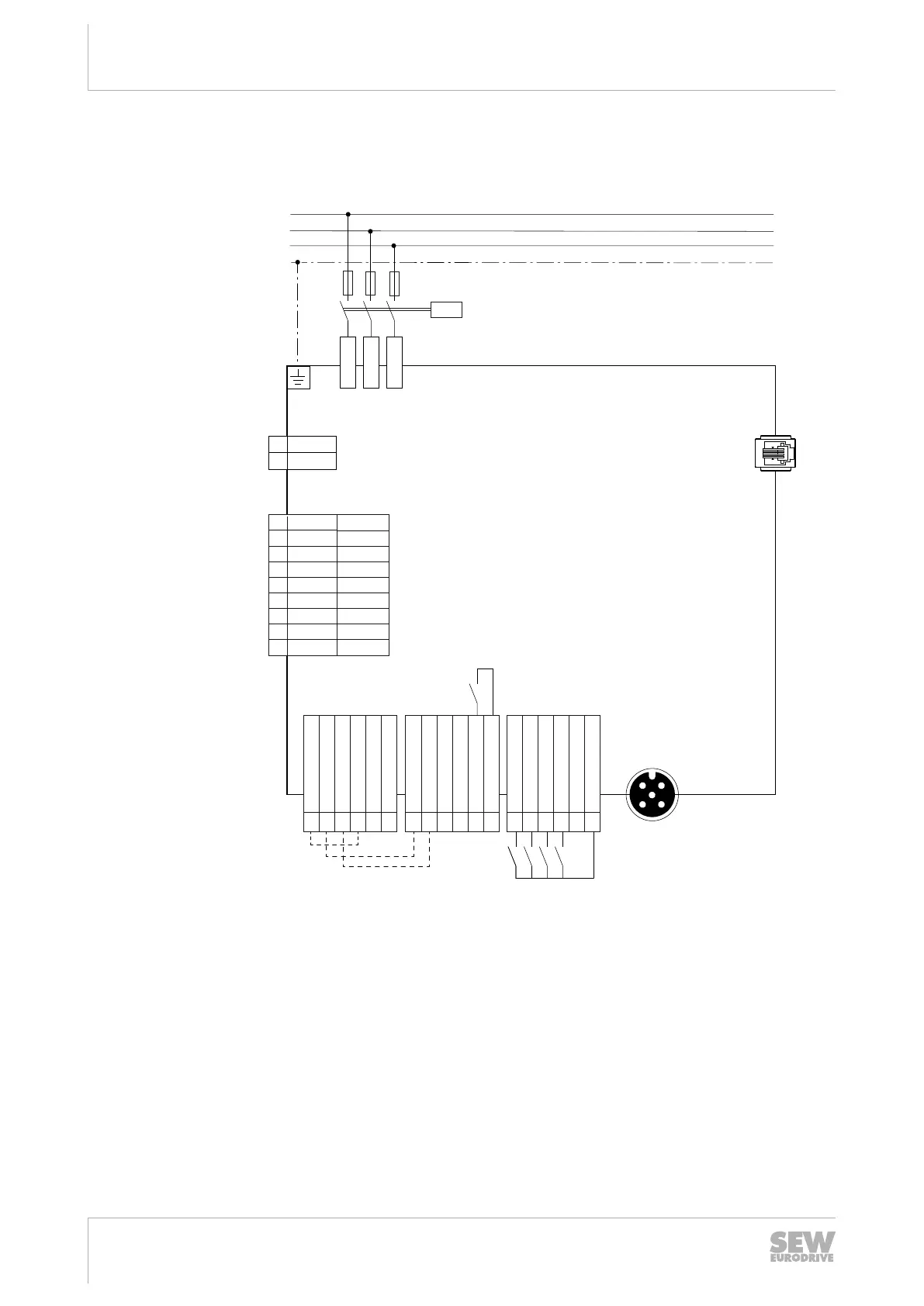
5.7 Connection diagram
The following figure shows the connections of the device:
L1
L2
L3
PE
K11
F11/F12/F13
L1
L2
L3
2 F_STO_P1
1 F_STO_P1
21 F_STO_P2
22 F_STO_P2
12 F_STO_M
11 F_STO_M
3 0V24_OUT
4 24V_OUT
23 0V24_IN
14 DOR-C
24 DOR-NO
25 0V24_OUT
26 24V_OUT
13 24V_IN
6 DI02
5 DI01
16 DI04
15 DI03
BW1
BW2
A1
/CO [1]
B B
A
–
C C
D D
U U
V V
W
T2
W
Temp-
/DI [1]
Temp+
14
13
15
U
V
W
X1 line terminals
X3 braking resistor
X2_A Terminals for motor,
brake and temperature sensor
X9 control terminals
X5231
X31 engineering interface
PE
MOVIMOT® flexible MMF1..-C/DBC.., MMF3..-C/DBC..
Analog input
[2]
30534403083
[1] Connection unit option, see chapter "Type designation connection unit"
[2] Jumpers installed at the factory for designs without plug connectors with STO
function. For additional information, refer to chapter "Functional safety".
For terminal assignment, refer to chapter "Terminal assignment".
For plug connector assignment, refer to chapter "Plug connectors".
29129451/EN – 12/2019
 Loading...