29 / 100
Siemens Commissioning Guide CM1G5192en
Building Technologies 5 Electrical installation 29.07.2010
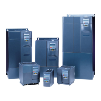
5.5 Interconnecting SED2 via RS-485
Note: If a 0 V signal is available on the BMS, ideally this should be connected to the 0 V terminal 2 of the SED2.
5.5.1 RS-485 bus termination
Buses not equipped with terminating resistors can cause errors in data communication. For this reason, the
RS-485 bus should be provided with a terminating resistor. This is accomplished via a network of resistors
connected to one end of the bus. We recommend to use active termination (3 resistors).
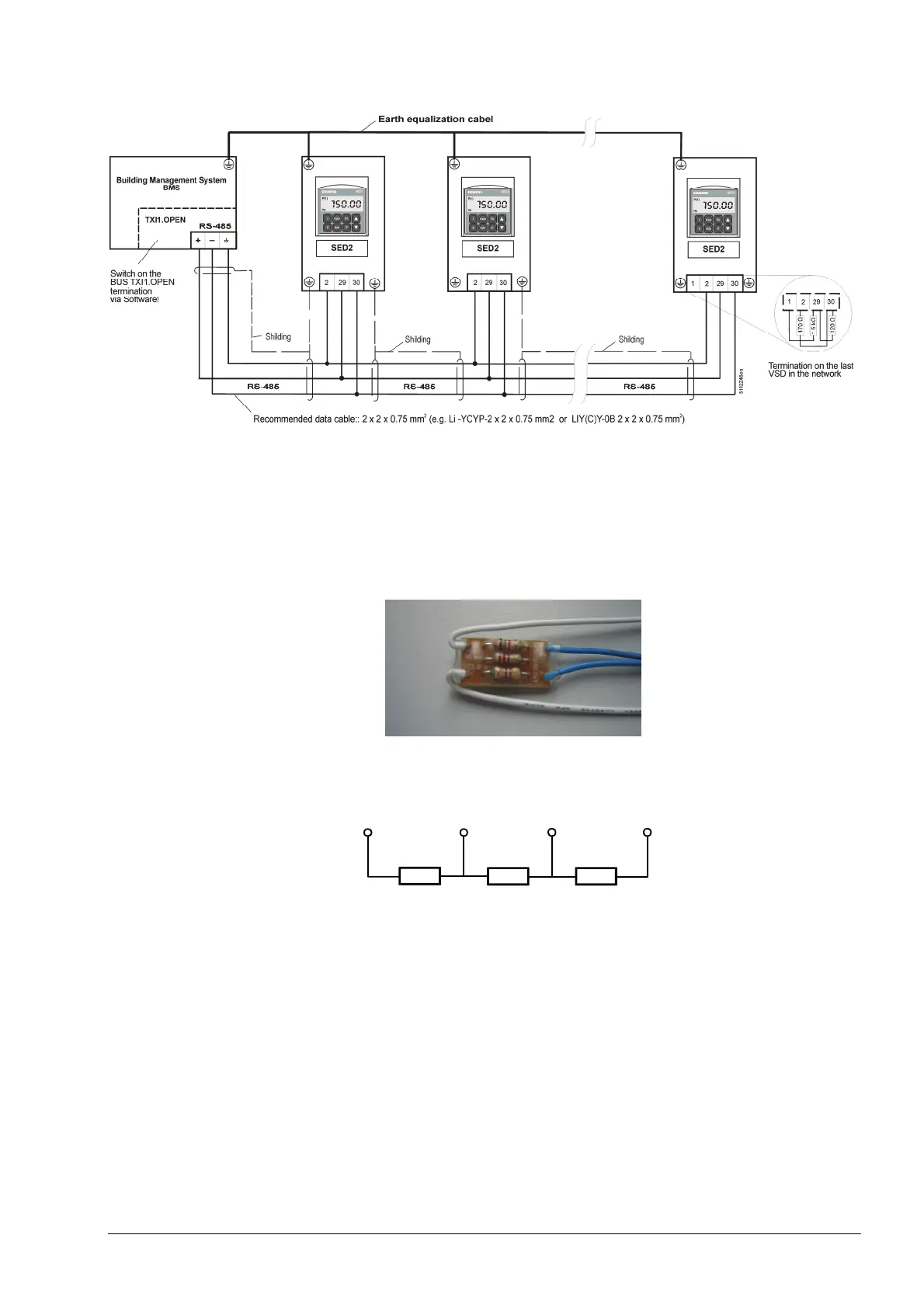
For that purpose, there is now a
network of terminating resistors
available, which can be ordered in
minimum quantities of 100 pieces
using ASN (type reference)
SED2-RS485-NT.
Connection of resistor network
The network of terminating
resistors is to be connected at
one end of the bus as illustrated
here.
1.5 k
Ω
120
Ω
470
Ω
5192V02
+10 V
Terminal 1
P+
Terminal 29
N-
Terminal 30
0V
Terminal 2
At the other end of the bus, only P+ and N- of the resistor network are to be connected, independent of whether it
is an SED2 or the BACS (Building Automation and Control System). In that case, connection of 0 V and +10 V is
not required.
 Loading...