31 / 100
Siemens Commissioning Guide CM1G5192en
Building Technologies 6 Commissioning 29.07.2010
6.1 DIP switch settings
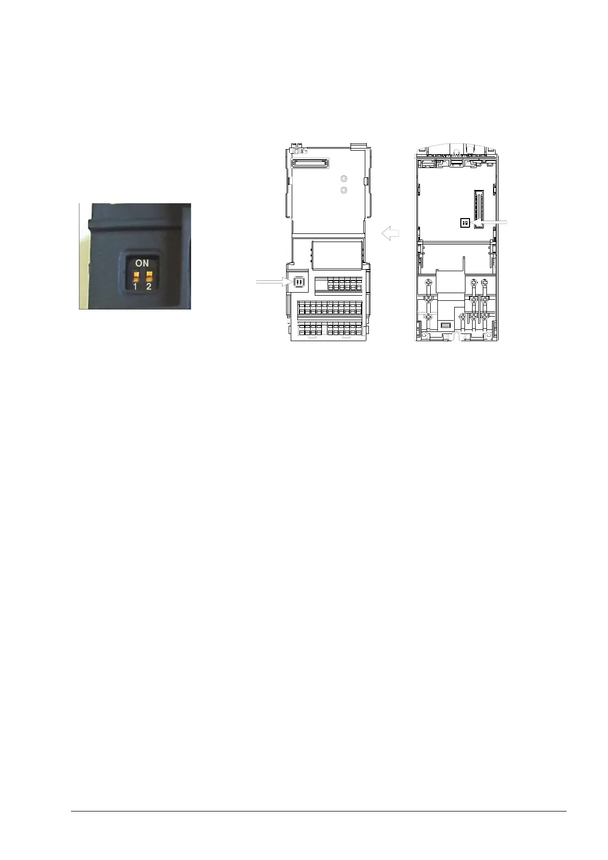
Location of the
DIP switches
For all versions of the SED2, the DIP switches used to configure the analog
inputs are located on the I/O board. The I/O board is located under the operator
panel, to which it is connected either directly (frame sizes A…C, IP20) or via a
cable (frame sizes D…E, and all IP54 models).
20 21 22 23 24 25
29 3017 26 27 2812 13 14 15 16
10 11678912345
ON
12
ON
12
DIP switches for
analog inputs
DIP switches
for setting
mains frequency
5192Z13en
I/O module
SED2 frame size A
In all versions of the SED2, the DIP switches for setting the mains frequency and
selecting US or European units of measurement are located on the control board
under the I/O module.
6.1.1 Setting the DIP switches on the I/O board
♦ DIP switch 1 Analog input 1: OFF position: Voltage 0…10 V
ON position: Current 0…20 mA
♦ DIP switch 2 Analog input 2: OFF position: Voltage 0…10 V
ON position: Current 0…20 mA
Factory setting for both DIP switches: OFF = voltage 0…10 V.
6.1.2 DIP switch settings on the control board
♦ DIP switch 2: OFF position: European default settings (50 Hz, kW, etc.)
ON position: North American default settings (60 Hz, hp, etc.)
Factory setting: OFF = 50 Hz
♦ DIP switch 1: Not for customer use. This switch must be in the OFF position
for correct functioning of the VSD
6.1.3 DIP switch settings on the AOP
Do not change the AOP DIP switch settings.
 Loading...