⑨ Exhaust air outlet. If appropriate connection of a 1" line,
max. length 20 m
⑩ Electrical line connection customer
⑪ Ex power relay SR853 ⑫ FS870S.702 mounting plate
⑬ Electrical line connection wall-mounted device ⑭ Electrical connections I/O customer
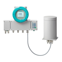
FigureB-1 Exp safety equipment, Gönnheimer ElektronikGmbH
Mounting instructions: When not in use, liquid gasket is applied to the purging gas outlet ⑦.
You will nd the information relevant for installation and operation of the Exp safety
equipment with the wall-mounted device in the corresponding manufacturer documentation.
The connection diagram shown refers to the example of the pressurized enclosure system
"F870S-HD" distributed by GönnheimerElektronikGmbH:
If you are using safety equipment from other manufacturers, contact your Siemens service
partner, if applicable.
Note
Exhaust air outlet
The connection to the exhaust air outlet provides a G 3/4" female thread. If appropriate attach
1" line via tubing adapter from G3/4" female to G1" female. Max. length of the line shall not
exceed 20m for straight laying.
B.1.1 Connection diagrams
B.1.1.1 Maintenance work
WARNING
Accumulation of potentially ammable gases
Explosion hazard
Potentially ammable gases can accumulate in the enclosure during maintenance work.
• Purge the enclosure with protective gas once maintenance work is complete.
Note
Optical signaling of the maintenance mode
To recognize the enabled maintenance mode (Bypass) of the Ex p safety equipment, we
recommend connecting an optical signaling on site.
Ex px safety equipment
B.1Overview
SIPROCESS GA700 rack and wall mounted devices
108 Compact Operating Instructions, 06/2023, A5E35134047-AB
 Loading...


