5.4.1 Recommended test setup
5.4.1.1 Recommended test setup for analyzer modules in all versions
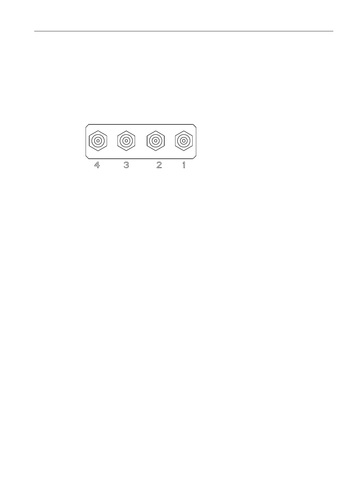
Arrangement of the gas connections in analyzer modules in all versions
The gure below is a schematic view of the gas connections:
1 Sample gas inlet
2 Sample gas outlet
3 ULTRAMAT 7: Reference gas outlet
OXYMAT 7 (high-pressure version) / CALOMAT 7: Not assigned, dummy plug
OXYMAT 7 (low-pressure version): Bypass outlet
4 OXYMAT 7 / ULTRAMAT 7: Reference gas inlet
CALOMAT 7: Not assigned, dummy plug
Figure5-1 Arrangement of the gas connections
Commissioning
5.4Checking gas paths for leaks
SIPROCESS GA700 rack and wall mounted devices
Compact Operating Instructions, 06/2023, A5E35134047-AB 69
 Loading...


