Note
Correct fastening of the cable glands
Fasten the cable glands as follows:
• M16 x 1.5 clamping range 5 to 10 mm (0.2" .. 0.39") made of plastic, counter nut and cap nut
(clamp cables or plugs) with a torque of 3.0 Nm.
• M20 x 1.5 clamping range 10 to 14 mm (0.4" .. 0.55") made of plastic, counter nut and cap
nut with a torque of 4.5 Nm.
• M16 x 1.5 clamping range 6 to 10 mm (0.2" .. 0.39") made of metal, counter nut and cap nut
with a torque of 6.5 Nm.
• M20 x 1.5 clamping range 10 to 14 mm (0.4" .. 0.55") made of metal, counter nut and cap
nut with a torque of 9.0 Nm.
To ensure tightness of cable glands, use cable diameters of:
• 5 mm .. 10 mm (0.2" .. 0.39") for cable glands M16x1.5
• 10 mm .. 14 mm (0.4" .. 0.55") for cable glands M20x1.5
7.1.3 OXYMAT 7
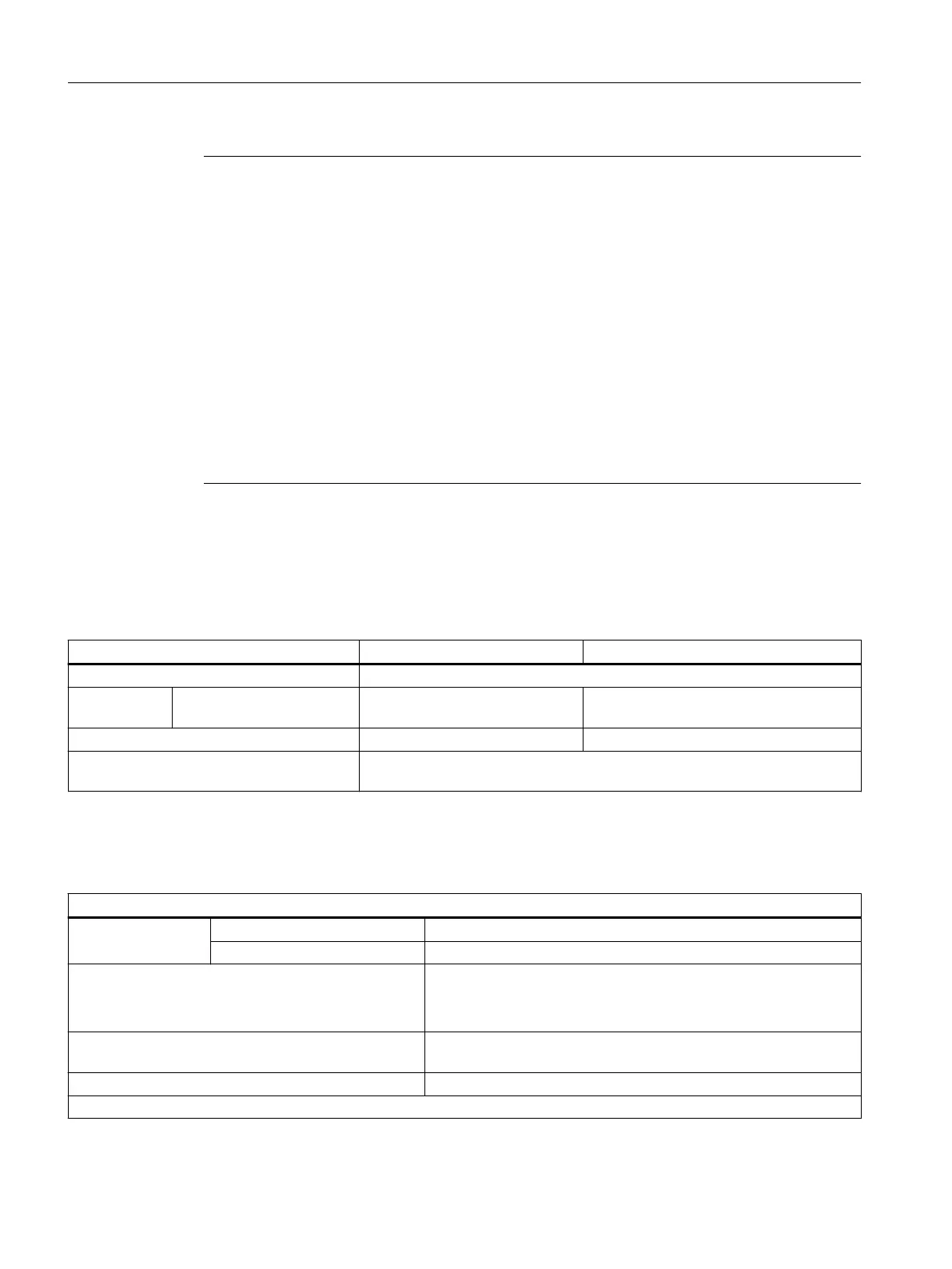
Table 7-10 OXYMAT 7: General technical data
General OXYMAT 7 OXYMAT 7 high-temperature
1)
Information on the smallest span See module nameplate or parameter sheet
Max. power
consumption
Warm-up phase ≤60W ≤120W
Weight (only module) < 5.5kg < 7.5kg
Max. EMC error during operation with one
and/or two OXYMAT7 / ULTRAMAT7 units
1.0% in accordance with EN61326-1
1)
The high-temperature version of the analyzer module is not intended for installation in the rack unit.
Table 7-11 OXYMAT 7: Gas inlet conditions
Gas inlet conditions
Sample gas pressure with internal pressure sensor -500 ... +1 500 hPa
with external pressure sensor -500 ... +2 000 hPa
Reference gas pressure
2000 to 4000 hPa above the sample gas pressure
1)
Max. permissible: 5000 hPa (abs.)
Only nitrogen is allowed with ammable gas as sample gas
Pressure loss between sample gas inlet and sample gas
outlet
<100hPa at 1l/min
Permissible sample gas ow range 18 to 60 l/h (0.3 to 1 l/min)
Sample gas temperature and humidity.
Technical data
7.1General technical specications
SIPROCESS GA700 rack and wall mounted devices
92 Compact Operating Instructions, 06/2023, A5E35134047-AB
 Loading...


