2-11. TX-167B Board (HDCU5500/HKCU-FB50)/TX-167A Board
(HDCU3500)
Tip
The TX-167A board is installed in HDCU3500. It can be removed in the same procedure as the TX-167B board.
Preparation
1. Remove the top cover. (Refer to “2-2. Top Cover”.)
2. Remove the optical cable. (Refer to step 1 in “2-4-1. LEMO Connector Assembly”.)
3. Remove the top chassis. (Refer to step 1 in “2-5. Top Chassis/Air Distributor Assembly”.)
4. Remove the optical multi fiber cable. (Refer to “2-4. Optical Multi Fiber Cable”.)
5. Remove the DC fan. (Refer to “2-9. DC Fan”.)
6. Remove the duct top. (Refer to step 1 in “2-12-1. Power Assembly”.)
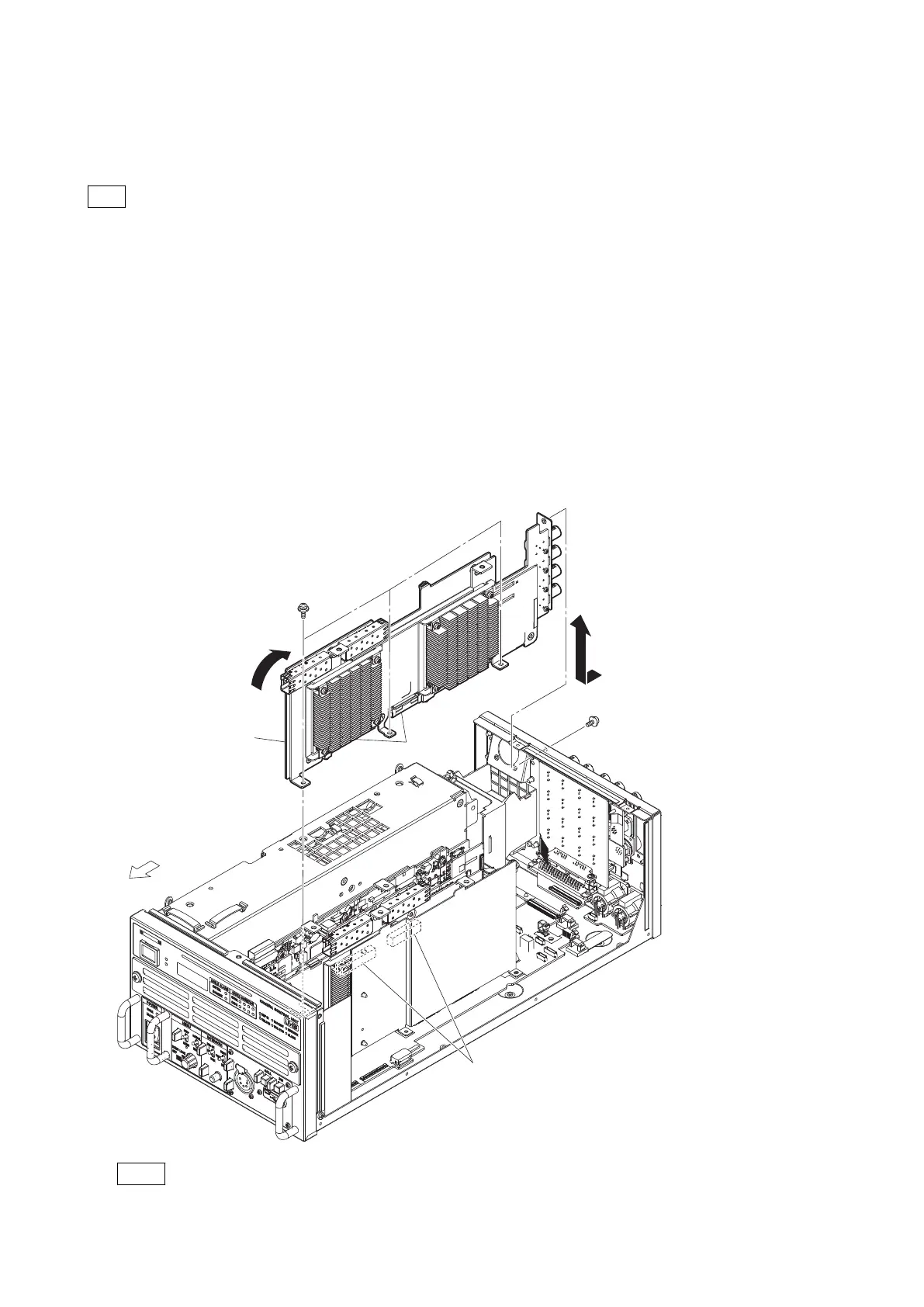
Procedure
1. Remove the four screws, and then slightly pull up the TX-167B board in the direction of the arrow (A) to disconnect
the B to B connectors.
2. Remove the TX-167B board in the direction of the arrow (B).
Front side
PSW
3 x 8
PSW
3 x 8
(B)
(a)
(b)
(c)
(d)
(A)
TX-167B board
B to B
connectors
B to B connectors
Note
When installing the TX-167B board, tighten the screws in the following sequence: (a), (b), (c), (d).
HDCU3500/HDCU5500
2-23
 Loading...


