2-15. Rear Panel
2-15-1. Rear Panel Assembly
Preparation
1. Remove the top cover. (Refer to “2-2. Top Cover”.)
2. Remove the DC fan. (Refer to “2-9. DC Fan”.)
3. Remove the AC inlet. (Refer to “2-13. AC Inlet”.)
Procedure
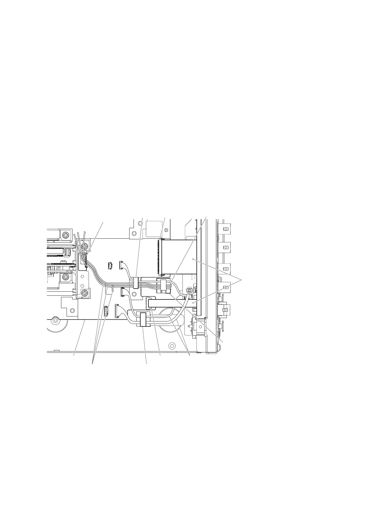
1. Disconnect the two fine-wire coaxial cables from the connectors (CN2000 and CN2001) on the VIF-75 board.
(Refer to step 1 in “2-6. VIF-75 Board”.)
2. Disconnect the fine-wire coaxial cable from the connector (CN600) on the SY-467 board.(Refer to step 1 in “2-7.
SY-467 Board/AT-195 Board”.)
3. Disconnect the flexible flat cable from the connector (CN010) on the MB-1257 board.
4. Disconnect the flexible flat cable from the connector (CN005) on the MB-1257 board.
5. Open the clamper and locking wire saddle [A], and then remove the harnesses and three fine-wire coaxial cables.
6. Remove the three fine-wire coaxial cables from the locking edge saddle.
7. Open the locking wire saddle [B], and then remove the two harnesses.
MB-1257 board
Locking wire saddle [B]
Fine-wire coaxial cables
Harnesses
Locking edge saddle
Clamper
Flexible flat cables
Harness
CN010
CN005
Locking wire saddle [A]
HDCU3500/HDCU5500
2-35
 Loading...


