245
To make a wipe pattern like a window blind
(Pairing)
Set the [Pairing] button to the on state and set the
fo
llowing parameter.
To add modulation to a pattern (Modulation)
In the [Modulation] group, select a modulation type.
H: Mod
ulate a pattern in the horizontal direction.
V: M
odulate a pattern in the vertical direction.
The modulation is set to a sine wave.
Set the following parameters.
Image Effect
Overview
Image effect is a function used to apply a DME effect to
the signal selected on the background A bus or B bus for
output.
• Setting the image effect function introduces a one-
f
rame delay in the image.
• In flip-flop mode, interchanging the background A bus
and
B bus signals also interchanges their image effect
settings at the same time.
DME restrictions
• To use the DME function, the MZS-X1610 3D DME
License (option) is required for each target box.
• When the system signal format is 2160P, the DME
f
unction must be enabled for use.
For details about setting GPU functions, see “Setting a
GPU” (page 363).
• The number of DME channels that can be used will
var
y, depending on the system signal format and the
DME enhanced function mode setting.
For details, see “DME channels” (page 194).
• The image effect function cannot be set when a
back
ground DME wipe is set.
Number of DME channels that can be used
si
multaneously
DMEs can be used in up to two locations simultaneously
on a
single switcher bank (processed key or image effect).
The number of DME channels that can be used on a key
depen
ds on the image effect use, as given below.
When not using the image effect function:
One DME channel on each of two keys, or one to four
DME
channels on a single key can be used.
When using the image effect function on background A or
B:
One DME channel on a single key only can be used.
When using the image effect function on both
back
ground A and B:
DMEs cannot be used on keys.
• In multi program 2 mode, DMEs can be used in up to
t
wo locations (main and sub).
• When M/E split is enabled, one DME channel can be
used
on each of the two sub blocks.
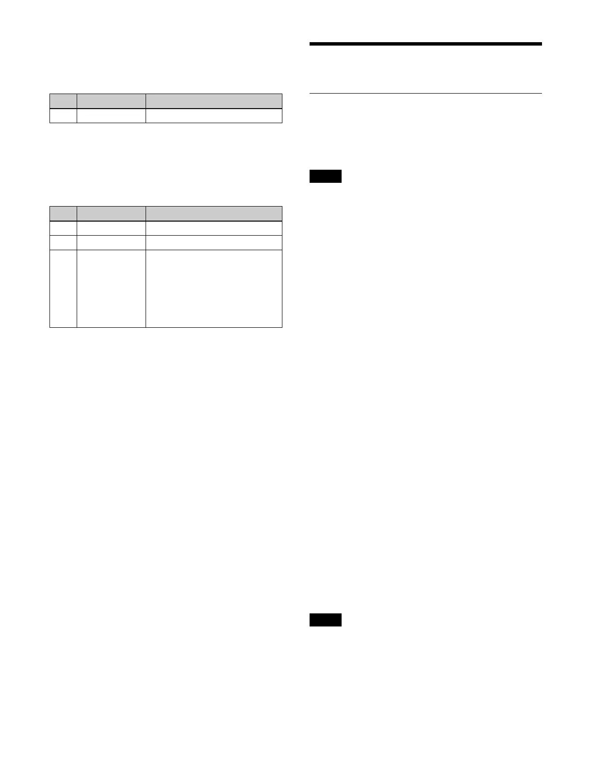
No. Parameter Adjustment
1 Width Width
No. Parameter Adjustment
1 Amplitude Amplitude of modulation
2 Frequency Frequency of modulation
3 Speed Speed of ripples
• Negative values create waves
i
n the down, left, and
counterclockwise directions.
• Positive values create waves in
t
he up, right, and clockwise
directions.
Notes
Notes
 Loading...


