Edition
2018
Workshop Manual
PARK PRO 340 IX
Chapter
4 Hydraulic system
Page
36
4.4 Transmission unit
4.4.1 List of components
13
12
12
6
11
11
13
11
4
1
3
2
9
5
7
8
ACB
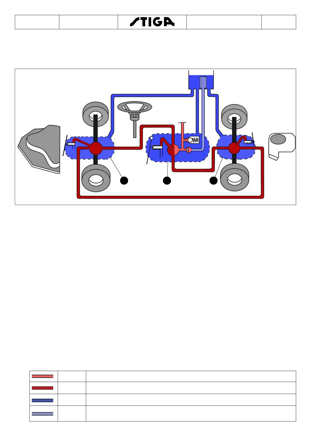
A. Rear transmission with own hydraulic motor (7).
B. Front transmission with own hydraulic motor (9).
C. Hydraulic pump. Parts 1,2,3 and 8 are positioned in the hydraulic pump.
1. Loading pump, max. 55 bar
2. Main pump
3. Pressure limiting valve for loading pressure
4. Fluid reservoir.
5. Fluid lter.
6. Auxiliary hydraulic circuit connectors (steering valve and accessories lifting device)
7. Hydraulic motor in rear transmission (A).
8. By-pass valve in the hydraulic pump (C).
9. Hydraulic motor in front transmission (A).
11. Return ow lines.
12. Delivery ow lines.
13. By-pass valve (used only for uid change operations)
Colour - Pressure
Red Delivery pressure to the main pump and the auxiliary hydraulic circuits.
Dark red Operating pressure to the hydraulic motors.
Blue Atmospheric pressure in the uid reservoir and vessels.
Light
blue
The pressure below atmospheric pressure (pump suction side).

 Loading...