Edition
2018
Workshop Manual
PARK PRO 340 IX
Chapter
4 Hydraulic system
Page
56
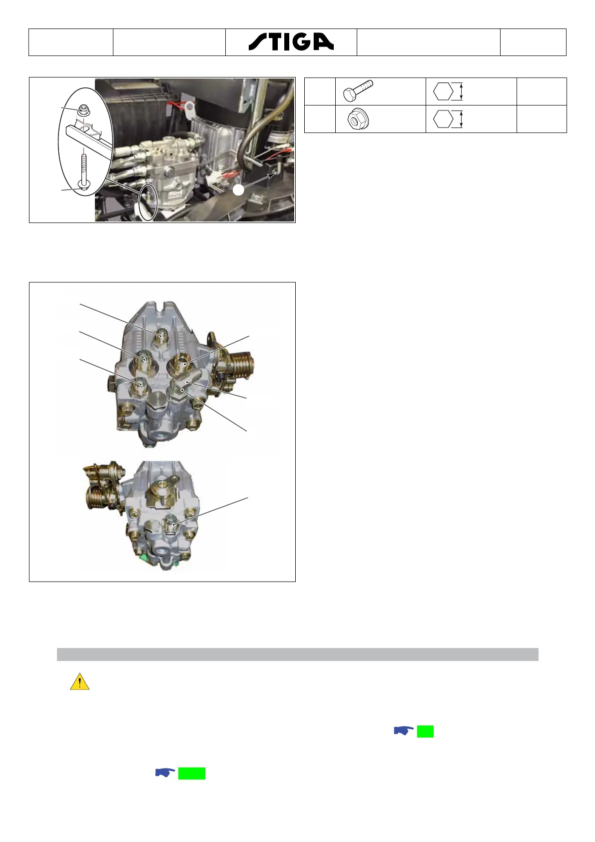
G (2x)
F (2x)
H
F
M10
17 mm -
G
M10 17 mm 35÷50 Nm
6. Remove the screws (F) and the anged nuts
(G).
7. Lift the pump (warning! the pump is full of uid)
and extract the control (H) from the mudguard
support.
4.9.1 Reassembly
A
40 Nm
78 Nm
40 Nm
40 Nm
78 Nm
78 Nm
Use a 14 mm and a 19 mm wrench.
1. Position and block the pump in a workbench
vice. Slacken the pump adapters.
2. Unscrew the adapters and insert them one at
a time in the corresponding seats on the new
pump. Check/replace the O-rings.
3. Tighten the adapters to the torque values
indicated in the gures.
4. When tightening the elbow adapter (A), adjust
to 45° down from the horizontal axis of the
pump.
5. Reassemble the various parts following the disassembly instructions in reverse order,
until all the hydraulic lines have all been installed. Check the condition of the O-rings and
replace them if damaged.
Caution!!!
After reinstalling the pump and connecting up all the hydraulic lines, before
proceeding take care to clean any parts which may have hydraulic liquid on
them.
6. Complete reassembly in all of its parts and adjust the cable.
6.4.
7. Once reassembly has been completed, turn on the machine and after a few minutes turn
it off (so that the uid ows into the circuit).
8. Filling with uid
4.8.2.

 Loading...