Edition
2018
Workshop Manual
PARK PRO 340 IX
Chapter
6 Control cables
Page
69
M
N
M
M5 8 mm 5 Nm
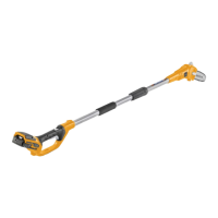
ENGINE SIDE
7. Slacken the terminal screw (M) on the engine
rear side and release the sheath and the ca-
ble.
8. Withdraw the cable (N) from the machine front
side.
6.4.2 Assembly
Note!
For cable installation, perform the disassembling procedures in reverse
order, taking care to perform these specic operations.
• Pour some oil drops on the two cable terminals and move the wire a few times inside its
sheath.
• Route the cable through the same previous cable path.
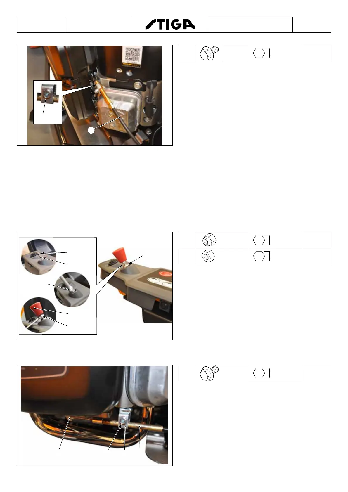
C
D
C
E
A
B
C
M8 13 mm 4 Nm
D
M5 8 mm 3 Nm
1. Insert the cable terminal (A) through the panel
hole.
2. Insert the O-ring (B).
3. Tighten the nut (C).
4. Tighten nut (C) and knob (E).
5. Adjust nut (D) and knob (E) positions.
6. Lock the knob (E) by means of nut (D).
7. Mount the new xing clamps in the exact point
of the previous ones.
6.4.3 Adjustment
B CD
A
A
M5 8 mm 5 Nm
1. Slightly tighten screw (A) of terminal (B) to
stop the sheath end.
2. Move the end of the cable (C) backwards /for-
wards on the clamp so that when the choke
command knob is moved, the lever (D) can
reach its open and closed end of stroke posi-
tion.
3. Tighten the screw (A).

 Loading...