Edition
2018
Workshop Manual
PARK PRO 340 IX
Chapter
1 General instructions
Page
4
1.1 Introduction
1.1.1 Limited liability
Despite the care and attention which has gone into the preparation of this manual, the
possibility of errors cannot be excluded. The author is not responsible for any information
which may be missing or incorrect. STIGA reserves the right to make changes to the
product at regular intervals without prior notice. The information provided in this manual is
based on data available at the time of publication. The drawings and photographs herein
may not completely match the machine you are working on in every detail.
1.1.2 How to read this manual
This manual is divided into chapters, headings and subheadings. The title of the paragraph
“2.1 Rear wheels” is a subheading in chapter 2 "Frame and safety guards" References to
titles or paragraphs are indicated with the abbreviation "chap." or "par." accompanied by
the relative number. Example: “chap. 2” or “par. 2.1”.
To facilitate consultation of the manual, each chapter is dedicated to a specic component.
There is a table of contents at the beginning of each chapter. The cover, on the other hand,
holds a general index of the chapters.
References to paragraphs or subheadings are indicated by the symbol
followed by
the paragraph / subheading number, e.g:
1.1.3.
1.1.3 Figures
To identify the various components in the gures, alphabetical “numbering” is used. In
each gure numbering begins with (A). An exception is made when a series of gures are
needed to describe an operation: in this case each component is given the same letter in
every gure it appears in.
1.1.4 Symbols, General warnings
This manual makes use of certain symbols. Their function is to bring the attention of
the reader to the most important notes so that he can carry out the operations with due
caution:
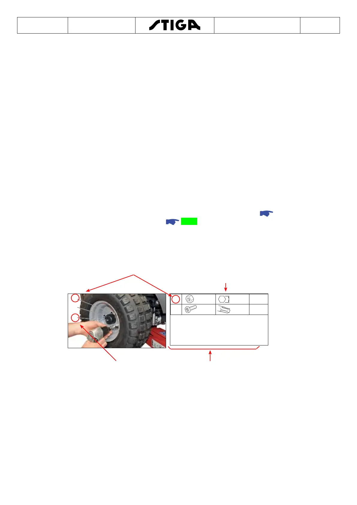
A
E
F
E
M10 16 mm 28 Nm
F
M5 T20 3÷4 Nm
7. Replace the stop ring (B).
8. Remove the hubcap (A).
8. Tighten the screw (F).
10. Replace the rear wheel.
11. Tighten the wheel nuts (E).
Reference to the position of
the screws in the drawing
The table provides, in a simple and
immediate way, all informations
concerning the screws used, the type of
the tool and the tightening torques
Location of the components
mentioned in the text
Descriptions of the gure

 Loading...