Edition
2018
Workshop Manual
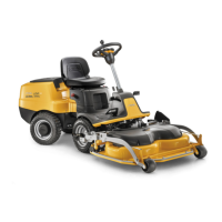
PARK PRO 340 IX
Chapter
4 Hydraulic system
Page
42
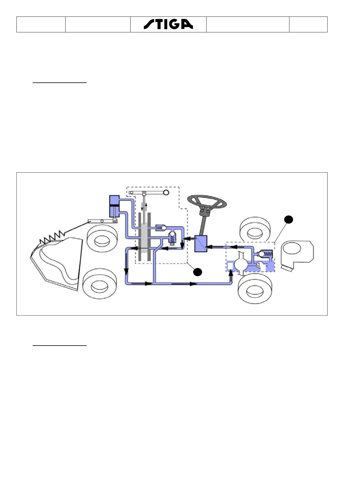
4.5.2 Operating description
Normal condition
Operating Status:
• Motor running at full speed.
• The steering wheel is not activated.
• The equipment lifting device is not activated.
The loading pump (1) forces the uid through the steering converter (5) and the open valve
(9).
The direction of uid ow is indicated by the arrows in the gure below. Being as neither
of the two components is in operation, the resistance may be ignored and the pressure is
very low (> 1bar).
In normal conditions the lift cylinder (11) is blocked in its neutral position as the uid cannot
ow out or in or because the uid lines are closed by the gate valve (9).
Steering wheel activated
Operating Status:
• Motor running at full speed.
• The steering wheel is activated.
• The equipment lifting device is not activated.
The loading pump (1) forces the uid through the steering converter (5) and the open valve
(9).
The direction of uid ow is indicated by the arrows in the gure below. From the moment
the steering converter (5) is in operation, a drop in upline pressure is generated.
The drop in pressure = the pressure in the red line - the pressure downline from the
steering converter (5). The drop in pressure depends on the steering force needed and is
limited by the incorporated valve (3).

 Loading...