Edition
2018
Workshop Manual
PARK PRO 340 IX
Chapter
6 Control cables
Page
70
6.5 HST control cable
6.5.1 Disassembly
1. Dismount the upper and lower front covers of the engine.
2.3.1
2. Remove the fuel tank 2.3.2.
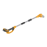
A
C
M6 10 mm 5 Nm
1. Remove the angle ball joint (A) from the HST
pedal (traction pedal).
6.2
2. Slacken the screws (C) from the cable xing
bracket (B).
3. Remove the cable from the bracket.
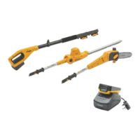
F
E
D
D
M6 10 mm 5 Nm
4. Unscrew the nuts (D) and remove the bracket
(E) xing the cable end.
5. Remove the angle ball joint (F) from the hy-
draulic pump.
6.2
6. Withdraw the cable from the front side, pass-
ing under the chassis.
6.5.2 Assembly
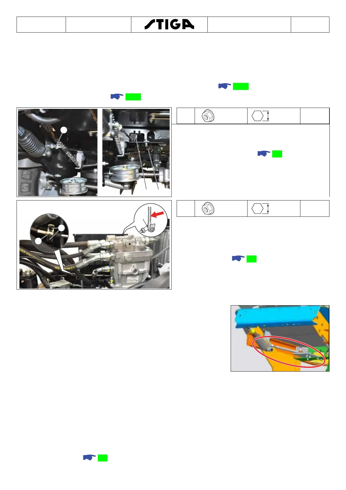
IMPORTANT NOTE - For machines built after 2015 until
November 2019, make sure all the latest updates for HST
drive cable supports, illustrated in the gure, have been
introduced, to eliminate any faults found in use. Should
these updates not have been implemented, THEY MUST be
performed using the specic kits and following the rel-
evant assembly instructions.
Note!
While reassembling the cable, keep the terminal rod longer on the control
pedal side. Refer to the direction arrow marked on the cable.
Note!
For cable installation, perform the disassembling procedures in reverse
order, taking care to perform these specic operations.
• Pour some oil drops on the two cable terminals and move the wire a few times inside its
sheath.
• Feed the cable inside starting from the machine front side.
• Check the angle ball joints, replace them if worn or damaged, special instructions shall
be observed
6.2.

 Loading...