Edition
2018
Workshop Manual
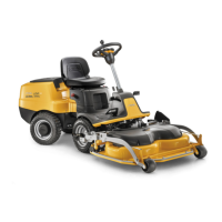
PARK PRO 340 IX
Chapter
7 Electrical system
Page
80
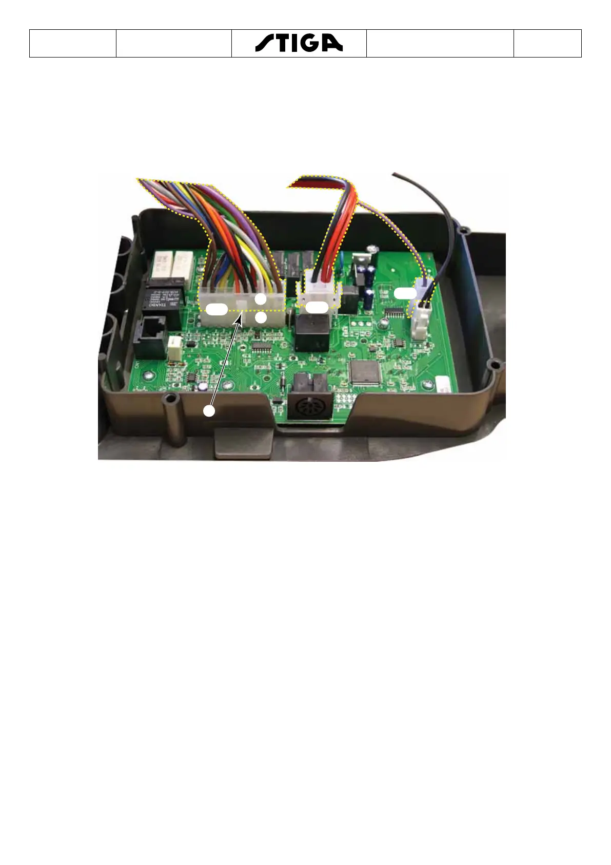
7.3 Electronic board
The electronic board shown below belongs to a machine model which is of a higher
class than the basic model dealt with in this manual, in any case the functions
described refer to the basic machine.
B
A
CN1
CN2
CN3
C
NOTE
For this machine version, the electronic card is connected to the system
by means of connectors CN1, CN2 and CN3.
The connectors are divided into two parts, the electronic card side and
the wiring side.
E.g.: connector CN1 is divided into (A) for the electronic side and (B) for
the wiring side.
The connector CN1 of the wiring is tted with a lug (C) which locks it onto the female
connector on the electronic card.

 Loading...