Edition
2018
Workshop Manual
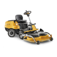
PARK PRO 340 IX
Chapter
4 Hydraulic system
Page
41
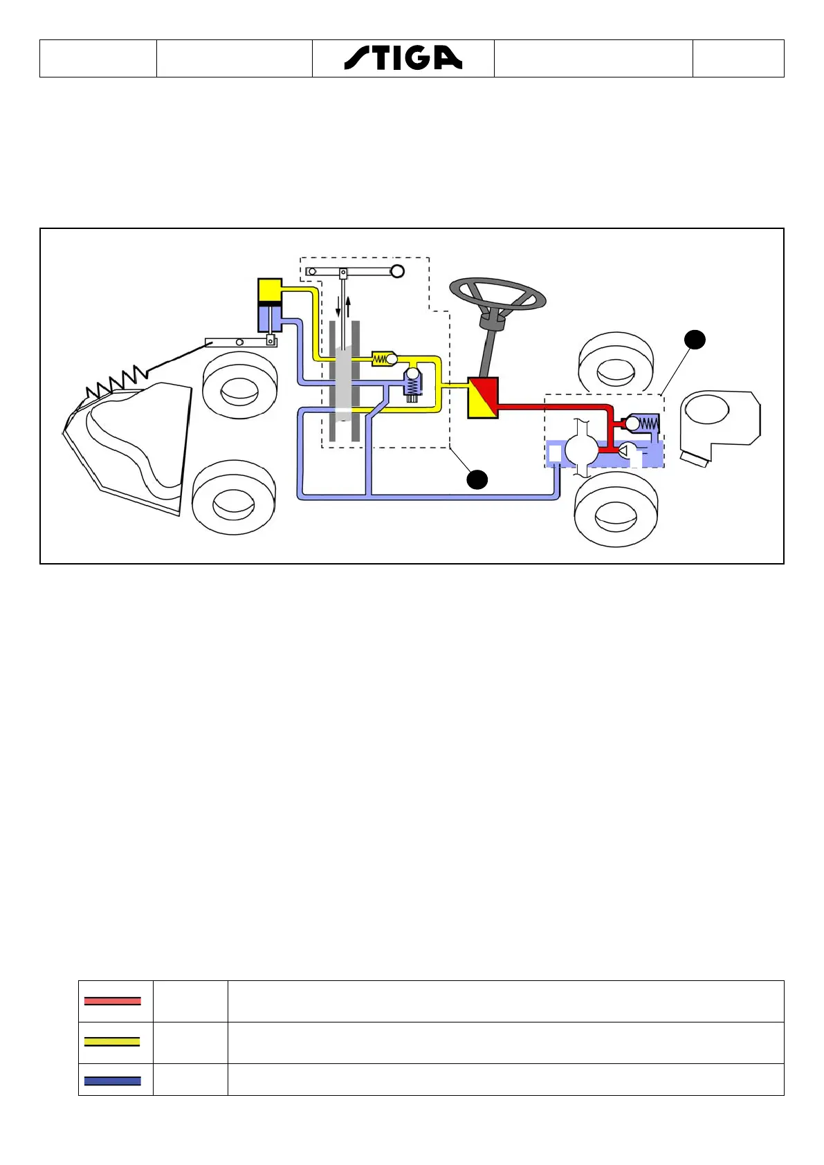
4.5 Hydraulic power steering and equipment lift
4.5.1 List of components
This section describes the physical conguration of the hydraulic components and the
different maximum pressures within the system.
A. The dashed-line box indicates the parts (from 1 to 4) which are incorporated in the hy-
draulic pump installed in front of the engine.
B. Manual valve unit (includes the components from6 to 10.
1. Loading pump
2. Main pump This pump is part of the driving system and provides pressure/uid ow.
3. Pressure limiting valve.
4. Fluid reservoir.
5. Steering torque converter.
6. Pressure limiting valve.
7. Pressure regulating screw.
8. Check valve.
9. Gate valve with 4 different passage congurations for the relative functions. Illustrated in
normal state.
10. Manual lever, connected to the gate valve.
11. Dual action lift cylinder
Colour - Pressure
Red
Indicates the total maximum pressure from the HST when the torque converter
(5) is in operation.
Yellow
Indicates the maximum pressure at the lift cylinder when equipment is being
lifted.
Blue Indicates uid return with low pressure (> 1 bar).

 Loading...