TB9100/P25 CG/P25 TAG Installation and Operation Manual Replacing Modules 101
© Tait Limited March 2014
7.4 Replacing a Reciter
Notice If the module that you are replacing is a crypto-capable reciter
or gateway module, zeroize the encryption keys before sending it away
for repair.
Removal 1. If you have not already done so, carry out the instructions in “Pre-
liminary Disassembly” on page 96, and remove the control panel, as
described in “Replacing the Control Panel” on page 98.
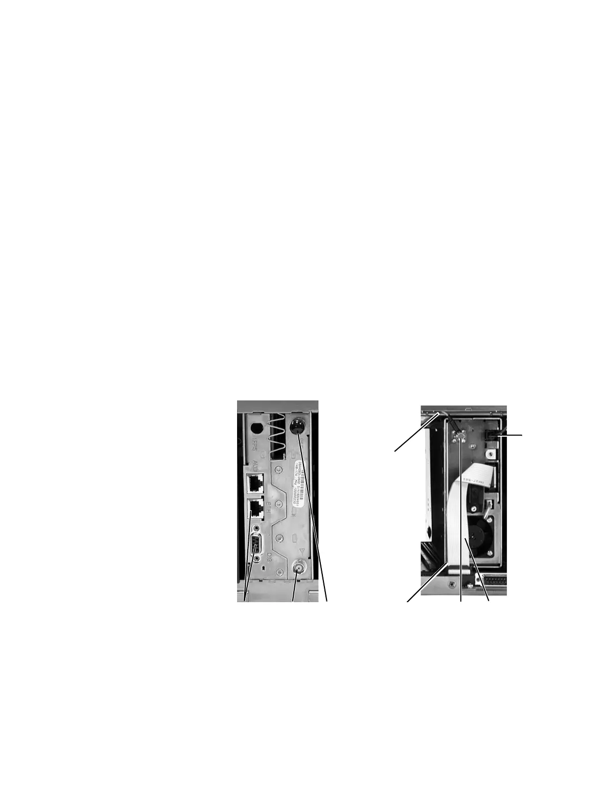
2. At the rear of the reciter, unplug the RF input cable
b, any system
cables
c and the external reference cable d (if fitted).
3. At the front of the reciter, unplug the DC input cable
e and the RF
output cable
f, and move both cables to one side. Unplug both ends
of the system control bus loom
g and remove it.
Notice The DC output connector on the subrack interconnect board
for reciter 2 is located in front of reciter 3. You will need to disconnect
reciter 2’s power cable from the subrack board before removing reciter 3.
4. Loosen the screw securing the retaining clamp
h and rotate the
clamp through 90° to clear the module.
5. Slide the reciter out of the subrack, taking care not to damage any of
the cables.
Refitting 1. Slide the replacement reciter into the subrack and secure it with the
retaining clamp.
2. Reconnect all the front and rear panel cables previously disconnected.
Ensure the front panel cables are retained by the cable retaining clips
j in the top of the subrack.
bcd gf
h
e
j
(obscured)

 Loading...


