TB9100/P25 CG/P25 TAG Installation and Operation Manual Operation 79
© Tait Limited March 2014
4 Operation
This section describes the control panel and shows how to operate its
microphone and speaker. It also indicates how to check that the fans are
operational and how to interpret indicator LEDs on modules.
4.1 Control Panel
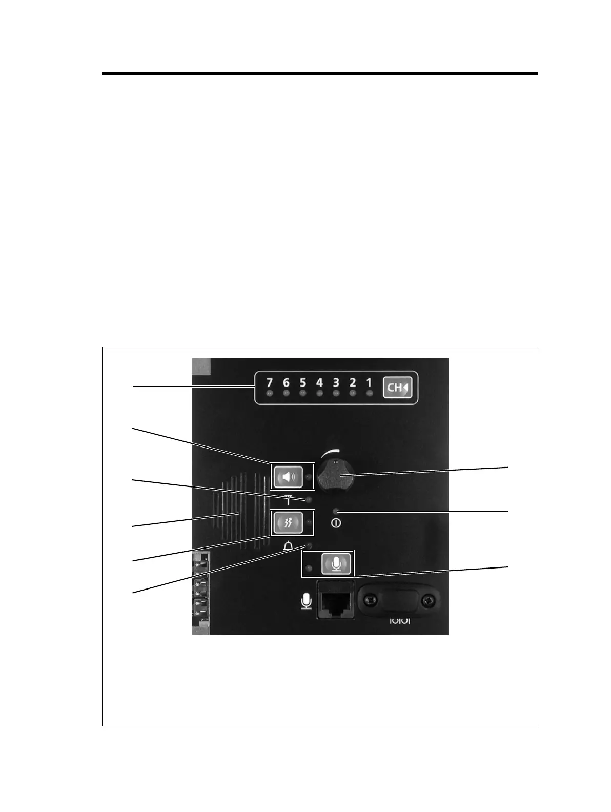
The operating buttons and indicator LEDs on the control panel are shown
in Figure 4.1. They allow some manual control over the base station and
monitoring of its operational status. The microphone and speaker allow the
maintainer to:
■ monitor voice traffic
■ communicate with the dispatcher and with SU users
Only the power and alarm LEDs are used in a gateway.
Figure 4.1 Operating controls on the control panel
b channel button and LEDs g alarm LED
c speaker button and LED h microphone button and LED
d receive LED i power LED
e speaker j speaker volume
f carrier button and transmit LED
e
d
c
b
f
h
i
j
g

 Loading...


